Unmanned aerial vehicle, antenna array based on unmanned aerial vehicle cluster, control system and control method

A technology of control system and flight control system, applied in the field of antenna array, control system and control, unmanned aerial vehicle, can solve the limitation of the working distance of the electronic system of the antenna array, it is difficult to achieve a large area, high gain antenna, and the size of the flight platform and weight limitations, to avoid low-elevation lobe splitting, increase direct-sighted distance, and improve coverage.

Inactive Publication Date: 2018-03-02
CHINA ELECTRONIC TECH GRP CORP NO 38 RES INST
View PDF5 Cites 5 Cited by
  • Summary
  • Abstract
  • Description
  • Claims
  • Application Information

AI Technical Summary

Problems solved by technology

For large antenna arrays with fixed ground sites, the size of the antenna array is relatively loose, and huge ground infrastructure can be used to ensure the installation layout and accuracy requirements of huge antenna arrays; and it is applied to moving platforms such as vehicles, aircraft, ships, or satellites. The physical size of a large antenna array on the Internet will be strictly limited, especially in the low frequency band, it is usually difficult to achieve a large-area, high-gain antenna, which limits the operating distance of the electronic system using the antenna array
[0007] In addition, for low-frequency antenna arrays, ground-based fixed stations can achieve large arrays and high gains. However, due to the strong influence of ground images, the radiation pattern of antenna arrays is prone to depressions or even zero points at low elevation angles, resulting in blind spots in beam coverage; while machine / satellite Although the carrier antenna array eliminates the ground effect, it is difficult to achieve a large antenna array and obtain high gain due to the size and weight of the flight platform.

Method used


Image

  • Unmanned aerial vehicle, antenna array based on unmanned aerial vehicle cluster, control system and control method
  • Unmanned aerial vehicle, antenna array based on unmanned aerial vehicle cluster, control system and control method
  • Unmanned aerial vehicle, antenna array based on unmanned aerial vehicle cluster, control system and control method

Examples


Embodiment 1

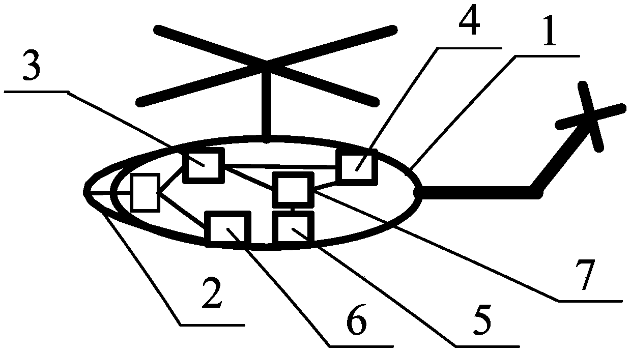
[0040] like figure 2 Shown, a kind of unmanned aerial vehicle 1, this unmanned aerial vehicle 1 is equipped with wireless communication system 3, satellite navigation system 4, remote control telemetry system 5 and flight control system 7; Carry out information exchange; the satellite navigation system 4 is used to obtain the position information of the drone 1; the position information is sent to the user terminal 8 through the remote control telemetry system 5, and the remote control telemetry system 5 receives the control command sent by the user terminal 8, and controls the The instruction is sent to the flight control system 7, and the flight control system 7 controls the flight of the UAV 1 according to the control instruction; the UAV 1 also carries an antenna unit 2 and a data transmission system 6, and the antenna unit 2 is a large-scale antenna array. As one of the components, the information data of the antenna unit 2 communicates with the user terminal 8 through t...

Embodiment 2

[0042] Such as figure 1 , 4 As shown in -8, an antenna array based on a UAV swarm includes a UAV swarm composed of at least two UAVs 1 and a user terminal 8 for remotely controlling the UAV swarm; each of which is unmanned Each drone 1 carries an antenna unit 2, and each drone 1 flies in formation under the control of the user terminal 8 to obtain the space layout required by the antenna array, so that the antenna unit 2 on each drone 1 forms a large antenna array; The information data of each antenna unit 2 communicates with the user terminal 8 through the data transmission system 6 provided on the drone 1 .

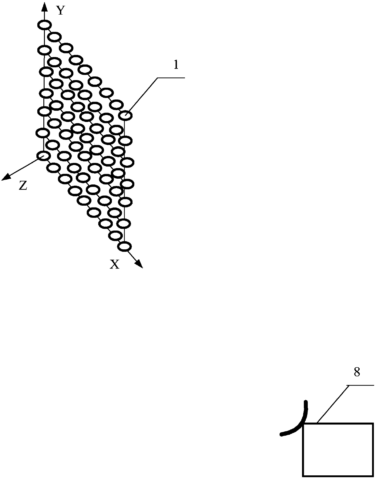
[0043] The antenna array composed of UAV cluster and antenna unit 2 is a single-layer planar array such as figure 1 , multi-layer planar array such as Figure 4 , 5 The two-layer planar array shown and Figure 6 , 7 The geese-shaped array or irregular three-dimensional array shown in Figure 8 shown.

Embodiment 3

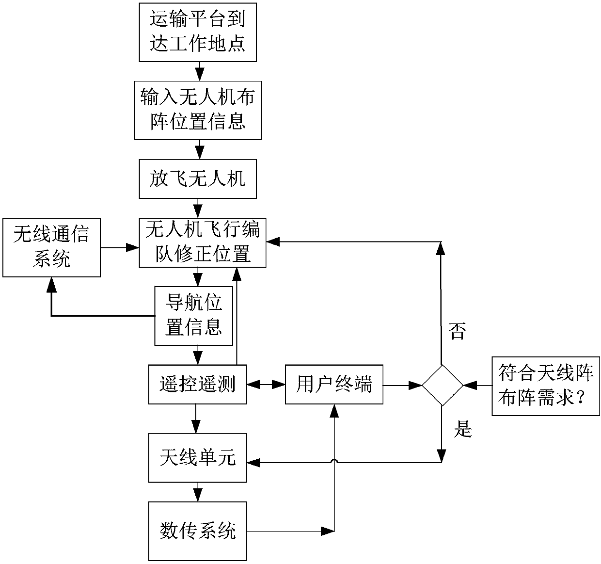
[0045] Such as image 3 As shown, the control system of the antenna array based on the UAV cluster described in Embodiment 2 includes a wireless communication system 3, a satellite navigation system 4, a remote control telemetry system 5 and a flight control system equipped with each UAV 1 7; the wireless communication system is used to establish an internal local area network with other drones 1 in the cluster to realize the information exchange of the drone cluster; the satellite navigation system 4 is used to obtain the position information of the drone 1; the remote control The telemetry system 5 is used to send the position information to the user terminal 8, and receive control instructions from the user terminal 8; the user terminal 8 can formulate the array position information of the UAV cluster, and generate Control instruction; the flight control system 7 is used to receive the control instruction and carry out flight control to the UAV 1 according to the control in...


PUM


Abstract

The invention belongs to the wireless communication technology field and especially relates to an unmanned aerial vehicle, an antenna array based on an unmanned aerial vehicle cluster, a control system and a control method. In the invention, a traditional fixed-arranged antenna array is split into several antenna units which can move freely, and the unmanned aerial vehicle is used to carry out scheduling. An antenna array size can be adjusted through a flying unmanned aerial vehicle cluster scale. A degree of freedom of array arrangement is large. The antenna array can control flight layout ofthe unmanned aerial vehicle, and reconstruct an antenna array shape and an antenna unit array arrangement mode according to a user terminal demand. Because restrictions of a large-scale antenna arraymechanical structure and a dimension envelope, and especially restrictions of motion platform weight and a volume are eliminated, a large-scale or ultra-large scale array surface can be acquired at alow frequency band. Therefore, a high gain capability is easy to acquire; the antenna array possesses a traditional amplitude and a phase weight variable and also possesses a weight capability of a space position adjusting change (such as a density weight) so that flexible and changeable directional diagrams can be realized, which includes a scanning range; and antenna array maneuverability is good.

Description

technical field [0001] The invention belongs to the field of radio technology, and in particular relates to an unmanned aerial vehicle, an antenna array based on an unmanned aerial vehicle cluster, a control system and a control method. Background technique [0002] The antenna array is an antenna form in which many antenna units are arranged according to certain rules and work together to improve the antenna capability. It is a very widely used radio frequency electronic system at present. Antenna arrays are mainly used in systems such as radar, communication, remote control telemetry, data transmission, reconnaissance and interference, and radio telescopes. [0003] The main parameters that determine the radiation performance of the antenna array include two categories: namely, the electrical parameters such as the amplitude, phase, operating frequency and bandwidth of the transmitted or received radio frequency signals that make up the antenna array radiating unit; the ot...

Claims


Application Information

Patent Timeline
Patent Type & Authority Applications(China)
IPC IPC(8): G05D1/10G05D1/00H01Q21/24H01Q23/00H01Q1/28
CPCG05D1/0022G05D1/0027G05D1/104H01Q1/28H01Q21/24H01Q23/00
Inventor 汪伟张洪涛罗健郑治陈明陈谦
Owner CHINA ELECTRONIC TECH GRP CORP NO 38 RES INST
Why Eureka
Try Eureka