An integrated electric power-assisted braking system

An electric power assist and braking system technology, applied in electric braking systems, brakes, electric vehicles, etc., can solve the problems of stuck, excessive mechanical resistance, high production cost, etc., to reduce the axial size and improve braking The effect of performance and convenient installation in real vehicles

Active Publication Date: 2019-01-18
JILIN UNIV
View PDF12 Cites 0 Cited by
  • Summary
  • Abstract
  • Description
  • Claims
  • Application Information

AI Technical Summary

Problems solved by technology

[0003] The system shown in the patent CN 104709096A uses a worm gear and a rack and pinion as a torque reduction mechanism. The transmission efficiency of the worm gear is low, the wear is serious, and the axial force of the worm is relatively large; A certain deflection force is generated, which can easily lead to excessive resistance or even jamming of the mechanism
Moreover, the force of the human and the motor cannot be decoupled, which may easily lead to system failure.
[0004] The system shown in the patent CN 104118416A adopts the single-stage deceleration of the nut ball screw, and the reduction ratio is small, so the requirements for the output power and output torque of the motor are relatively high, so the motor size is large and the production cost is high; in addition, because the rotor of the motor Not secured so it can deflect causing excessive radial force
[0005] The system shown in patent CN 106240552A adopts a two-stage transmission mode of spur gears and nut ball screws, but due to the large number of transmission pairs, the axial dimension of the entire system is relatively long, which is not conducive to the layout of the vehicle

Method used


Image

  • An integrated electric power-assisted braking system
  • An integrated electric power-assisted braking system
  • An integrated electric power-assisted braking system

Examples


Embodiment Construction

[0031] The present invention is described below in conjunction with accompanying drawing:

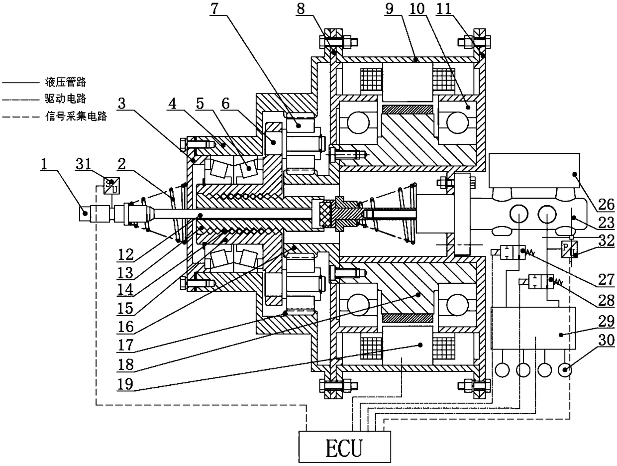
[0032] refer to figure 1 , an integrated electric power-assisted braking system according to the present invention includes a motor housing 9 , a planetary gear housing 4 and a middle end cover 8 . Take the direction of the driver's braking force input as the front. The rear end face of the planetary gear housing 4, the middle end cover 8, and the front end face of the motor housing 9 are evenly distributed with four threaded holes of the same specification. The front end faces of the machine housing 9 are connected by bolts and nuts. The front end of the planetary gear housing 4 is covered by a front end cover 3, and the two are connected by screws.

[0033] refer to figure 1 , the motor housing 9 is provided with a motor, the motor includes a motor stator 19 and a motor rotor 18, the front section of a hollow stepped shaft-shaped rear end cover 11 is a small journal section, and t...


PUM


Abstract

The invention provides an integrated electric power-assisted braking system. The integrated electric power-assisted braking system comprises a motor, a planet gear set and a ball screw mechanism; a planet wheel in the planet gear set is connected with a nut in the ball screw mechanism; a pedal push rod is connected with an output shaft of a main cylinder through an elastic reaction disk and a power-assisted push rod; a pedal travel sensor is arranged on the pedal push rod; the main cylinder is connected with a hydraulic control unit through a hydraulic pipeline, a pressure sensor and two two-position two-way electromagnetic valves; the hydraulic control unit is connected with four disk brakes on a vehicle through brake pipelines; and the pedal travel sensor, the two-position two-way electromagnetic valves, the hydraulic control unit and the pressure sensor are connected with an electronic control unit of the vehicle. By using the motor as a power source, a speed reducing and torque increasing effect is realized by using a two-stage transmission mechanism and rotation output of the motor is converted into translation output; therefore, the integrated electric power-assisted brakingsystem has the advantages of large transmission ratio, high transmission accuracy, high transmission efficiency and compact structure.

Description

technical field [0001] The invention belongs to the field of automobile braking devices in the field of vehicle engineering, and relates to an integrated electric power-assisted braking system. Background technique [0002] With the rapid development of electric vehicles and smart vehicles, the traditional vacuum booster hydraulic braking system can no longer meet the requirements. Since the electric power-assisted braking system cancels the vacuum booster commonly used in traditional vehicles, and can realize the decoupling of frictional braking force and regenerative braking force, and has a simple structure and convenient layout, it will become an inevitable direction for the development of braking systems. [0003] The system shown in the patent CN 104709096A uses a worm gear and a rack and pinion as a torque reduction mechanism. The transmission efficiency of the worm gear is low, the wear is serious, and the axial force of the worm is relatively large; A certain defle...

Claims


Application Information

Patent Timeline
Patent Type & Authority Patents(China)
IPC IPC(8): B60L7/24B60T13/74
CPCB60L7/24B60T13/746
Inventor 朱冰田海舰赵健张培兴赵冠宇武维祥闫淑德
Owner JILIN UNIV
Why Eureka
Try Eureka