
Device for preheating waste steel and alloys by using converter steel slag afterheat and application method

A technology of converter steel slag and heating method, which is applied in the field of steelmaking, can solve problems such as deterioration of molten steel quality, reduction of iron and manganese yield, and increase of slag amount, so as to avoid temperature inconsistency, facilitate use and operation, and reduce production cost Effect

Active Publication Date: 2018-03-09
ANGANG STEEL CO LTD
View PDF5 Cites 15 Cited by
  • Summary
  • Abstract
  • Description
  • Claims
  • Application Information

AI Technical Summary

Problems solved by technology

In order to increase the ratio of scrap to steel, the traditional method is to add heating agents to the converter, which are divided into metal series and carbon series. The use of metal heating agents, such as ferrosilicon alloy and aluminum, will increase the amount of slag and the yield of iron and manganese. Reduce; the use of carbonaceous heating agents, such as heavy oil, diesel, coke, anthracite, etc., will increase the sulfur and ash content and deteriorate the quality of molten steel
Although the thermal compensation technology of the secondary combustion oxygen lance developed in recent years can increase the ratio of steel scrap, the application of this technology is still immature, and many enterprises have not yet had the conditions to adopt these technologies

Method used


Image

  • Device for preheating waste steel and alloys by using converter steel slag afterheat and application method
  • Device for preheating waste steel and alloys by using converter steel slag afterheat and application method
  • Device for preheating waste steel and alloys by using converter steel slag afterheat and application method

Examples


Embodiment Construction

[0026] The present invention will be described in further detail below in conjunction with the accompanying drawings.

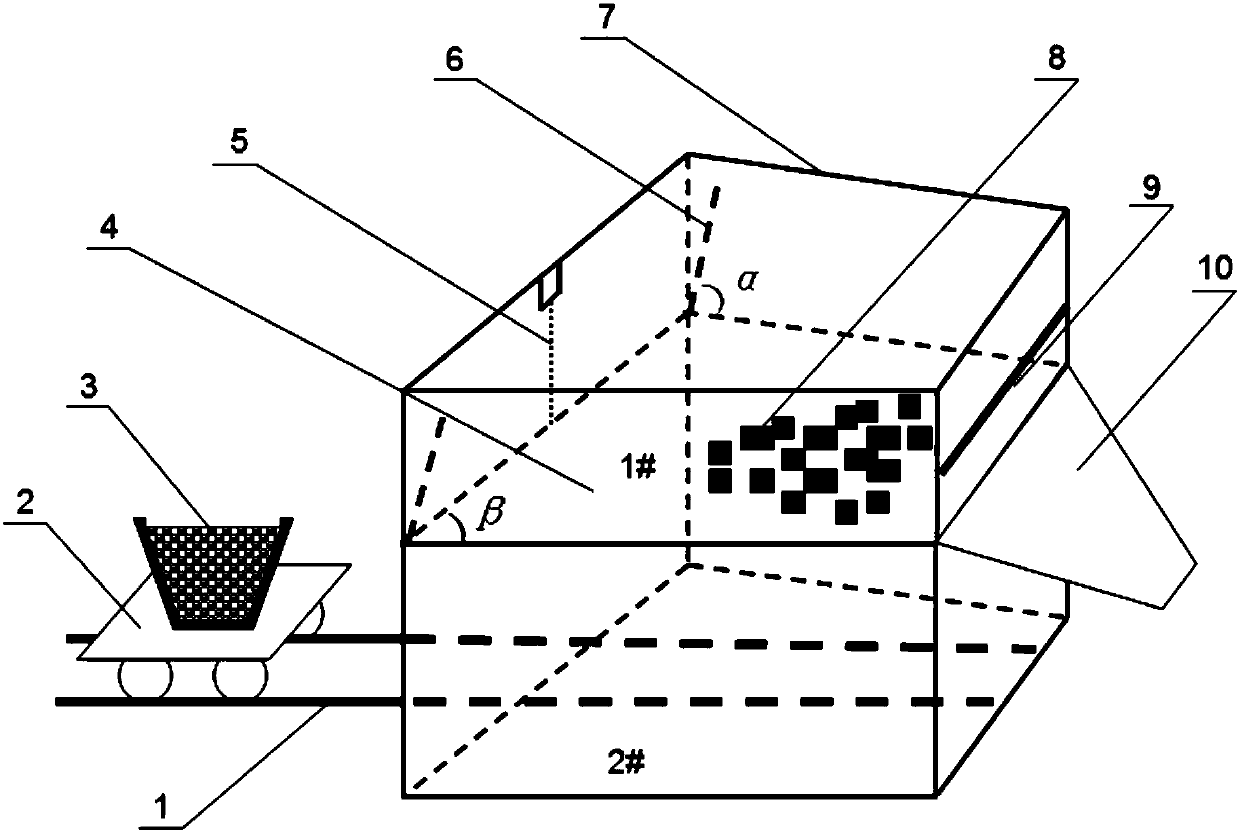
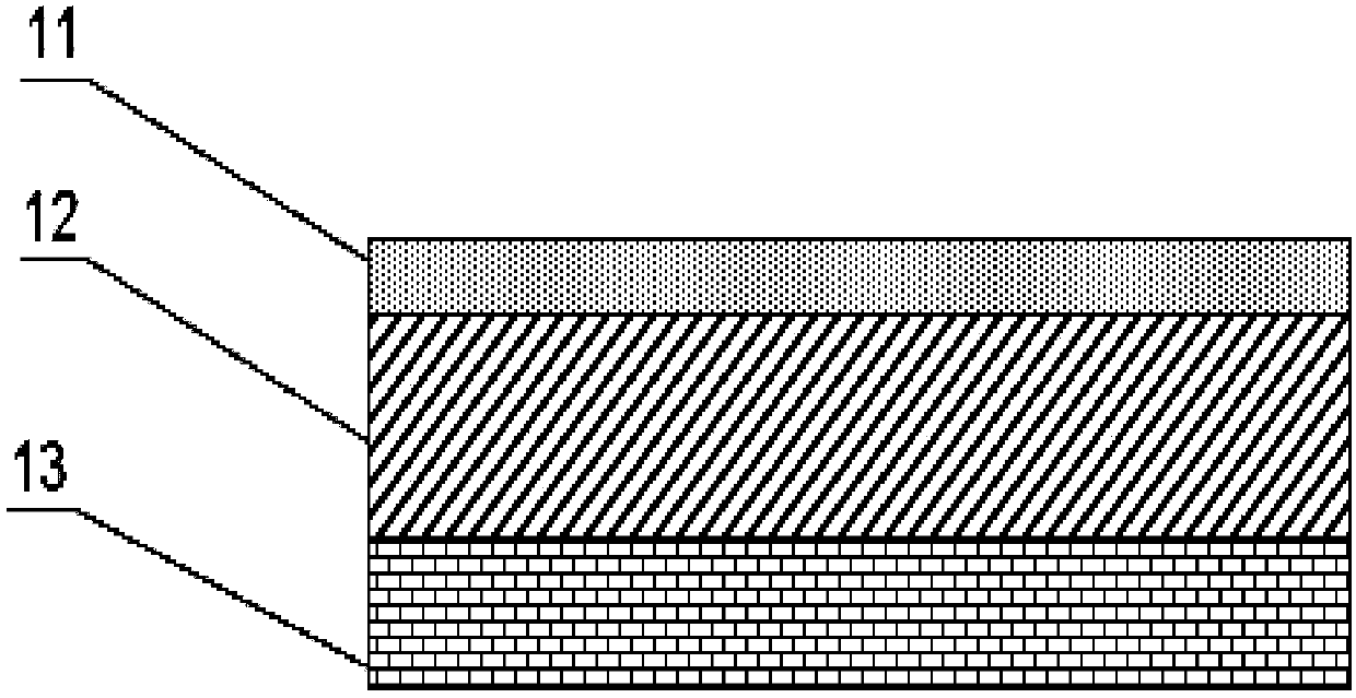
[0027] A device for preheating steel scrap and alloys using the residual heat of converter steel slag. The main body is composed of upper and lower chambers respectively 1# chamber and 2# chamber. figure 1 shown. Among them, 1# room is the scrap steel adding room, 2# room is the high-temperature slag storage room, and the walls of 1# room and 2# room are three-layer structure. The schematic diagram is as follows figure 2 As shown, the inner layer 11 of the four walls is a 30mm thick high temperature resistant cast iron layer, the middle layer 12 of the four walls is a 200mm thick heat-insulating refractory material layer, and the outer layer 13 of the four walls is a 70mm thick ordinary clay brick layer. The slag tank 3 with high-temperature steel slag can sit on the slag tank trolley 2, and transport the slag tank 3 with high-temperature steel slag to the ...


PUM

PropertyMeasurementUnit
thicknessaaaaaaaaaa
thicknessaaaaaaaaaa
thicknessaaaaaaaaaa

Abstract

The invention discloses a device for preheating waste steel and alloys by using converter steel slag afterheat and an application method. The device mainly consists of a waste steel and alloy adding chamber 1# chamber and a high-temperature furnace slag storage chamber 2# chamber. An insulation cover plate covers the top of the 1# chamber; the lower part of the 1# chamber is a baking chamber baseplate with a double-layer structure; a baseplate overturning driving hydraulic lifting chain is arranged above the top edge of the baseplate; overturning guide rails forming included angles alpha withthe baseplate are arranged on two side walls; and a discharge door is arranged on the back side wall. A slag tank car rail is arranged in the 2# chamber; and the top is the baseplate of the 1# chamber. In the use process, the cover plate at the top of the 1# chamber is opened to put the waste steel or the alloys on the baseplate; the insulation cover plate is covered; and then, a high-temperatureslag tank is conveyed to the 2# chamber through a slag tank car to finish baking heating of the waste steel or the alloys. Through use of the device, the converter high-temperature furnace slag afterheat can be recycled, and meanwhile, the effects of increasing the converter waste steel ratio, reducing the cost and improving the efficiency are achieved.

Description

technical field [0001] The invention belongs to the field of steelmaking, and in particular relates to a device and a use method for preheating scrap steel and alloys by using the residual heat of converter steel slag. Background technique [0002] During the converter smelting process, the high-temperature liquid steel slag produced generally accounts for about 12% to 15% of the converter’s charging capacity. For a converter with a charging capacity of 100 tons, the entire smelting process will produce 12 to 15 tons of high-temperature molten steel slag. state steel slag. The temperature of high-temperature slag is usually around 1600°C, which contains a lot of heat. Because this part of the heat is difficult to store, most steel mills use slag splashing and water cooling in the open air to cool down the slag or cool it naturally, and transport it to the slag yard for storage after the temperature drops to 80°C to 100°C. Individual steel mills use the hot-splash method in...

Claims


Application Information

Patent Timeline
Patent Type & Authority Applications(China)
IPC IPC(8): C21C5/46F27D17/00
CPCC21C5/46F27D17/004F27M2003/13Y02P10/25
Inventor 李德军朱晓雷王爽李晓伟于赋志许孟春刘祥黄玉平吕春风康伟
Owner ANGANG STEEL CO LTD
Learn More