Frequency-reconfigurable microstrip patch yagi antenna and reconstruction method

A Yagi antenna and microstrip patch technology, applied in the microwave field, can solve the problems of high processing technology, material fatigue, poor durability, etc., and achieve the effect of saving liquid crystal materials, reducing processing difficulty, and good effect

Inactive Publication Date: 2018-03-09
UNIV OF ELECTRONICS SCI & TECH OF CHINA
View PDF5 Cites 17 Cited by
  • Summary
  • Abstract
  • Description
  • Claims
  • Application Information

AI Technical Summary

Problems solved by technology

However, MEMS also has its own disadvantages. For example, MEMS itself is a mechanical structure, so multiple switches will cause a certain degree of material fatigue, resulting in poor durability compared with integrated components such as PIN diodes.
At the same time, MEMS is also the same as the PIN diode, which can only provide two state conversions.
Although MEMS has a high degree of integration and excellent frequency response characteristics, its processing technology requirements are higher than those of lumped parameter components.
As a commonly used electromagnetic material, ferroelectrics have also been extended to electrically adjustable antennas, but compared with MEMS, their high loss is still a problem to be solved.

Method used


Image

  • Frequency-reconfigurable microstrip patch yagi antenna and reconstruction method
  • Frequency-reconfigurable microstrip patch yagi antenna and reconstruction method
  • Frequency-reconfigurable microstrip patch yagi antenna and reconstruction method

Examples


Embodiment 1

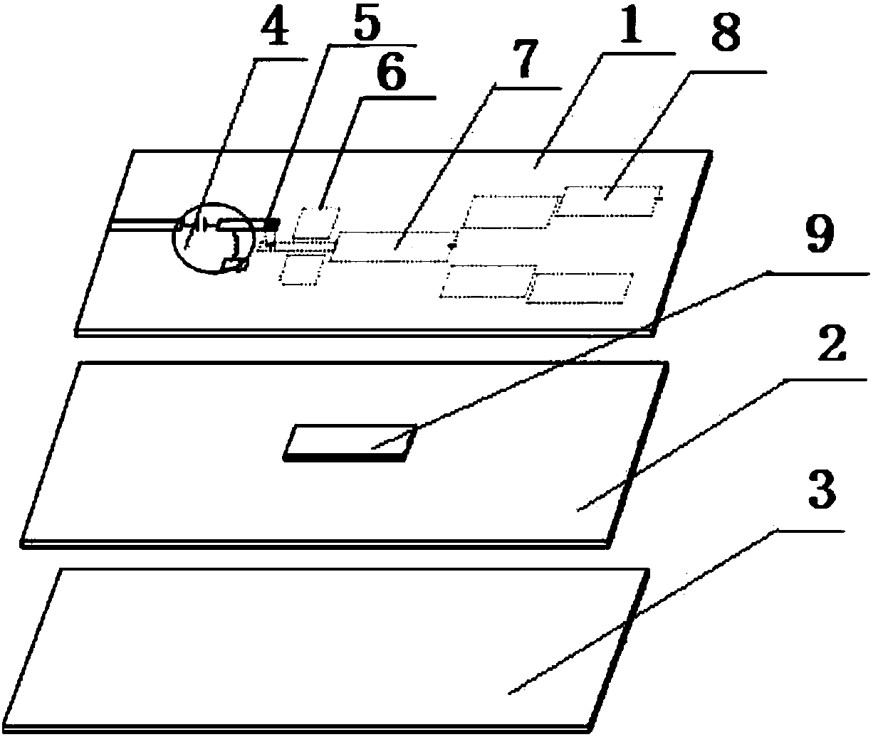
[0027] Such as Figure 1-4 As shown, the present invention includes a frequency reconfigurable microstrip patch Yagi antenna, including a three-layer structure, the first layer structure includes a first layer of dielectric substrate 1, and a coupled microstrip line is arranged on the upper surface of the first layer of dielectric substrate , DC bias circuit 4 and metal through hole 5, install impedance conversion line, reflective patch 6, active patch 7 and guide patch 8 on the lower surface of the first layer of dielectric substrate, active patch 7 is connected to impedance At one end of the conversion line, the radio frequency signal is coupled to the impedance conversion line by the coupled microstrip line, and the DC passes through the DC bias circuit, and is loaded to the active patch through the metal through hole; the second layer structure includes the second layer of dielectric substrate 2 and the liquid crystal cavity Body 9, the liquid crystal cavity is filled with...

Embodiment 2

[0030] This embodiment is preferably as follows on the basis of Embodiment 1: the DC bias circuit includes an inductor and a capacitor, the capacitor is set at the end of the coupled microstrip line to receive the RF signal, and the inductor is set behind the capacitor to avoid the influence of the DC circuit on the RF signal . The setting of the capacitor can effectively protect the test circuit.

[0031] The liquid crystal material is a nematic liquid crystal. When the nematic liquid crystal is in the nematic phase, the molecular orientation has a long program. Nematic liquid crystal molecules have dielectric anisotropy, and the alignment direction of the molecules will be deflected under an external electric field. Dielectric anisotropy can be positive or negative, but for liquid crystals in the microwave band, usually the vertical component of the effective dielectric constant is smaller than the parallel component, so the dielectric anisotropy is positive.

[0032] Thi...

Embodiment 3

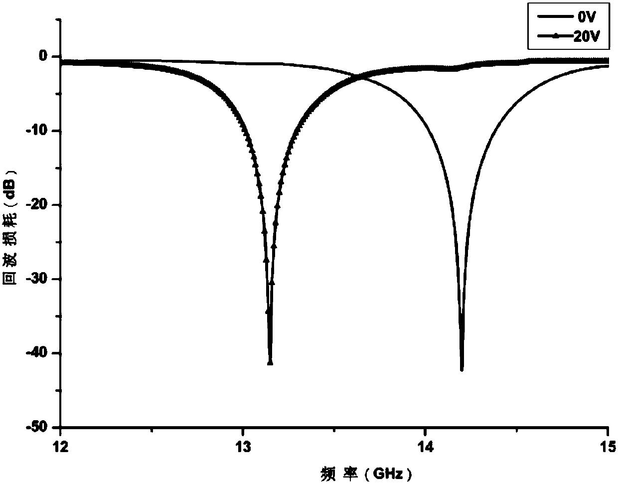
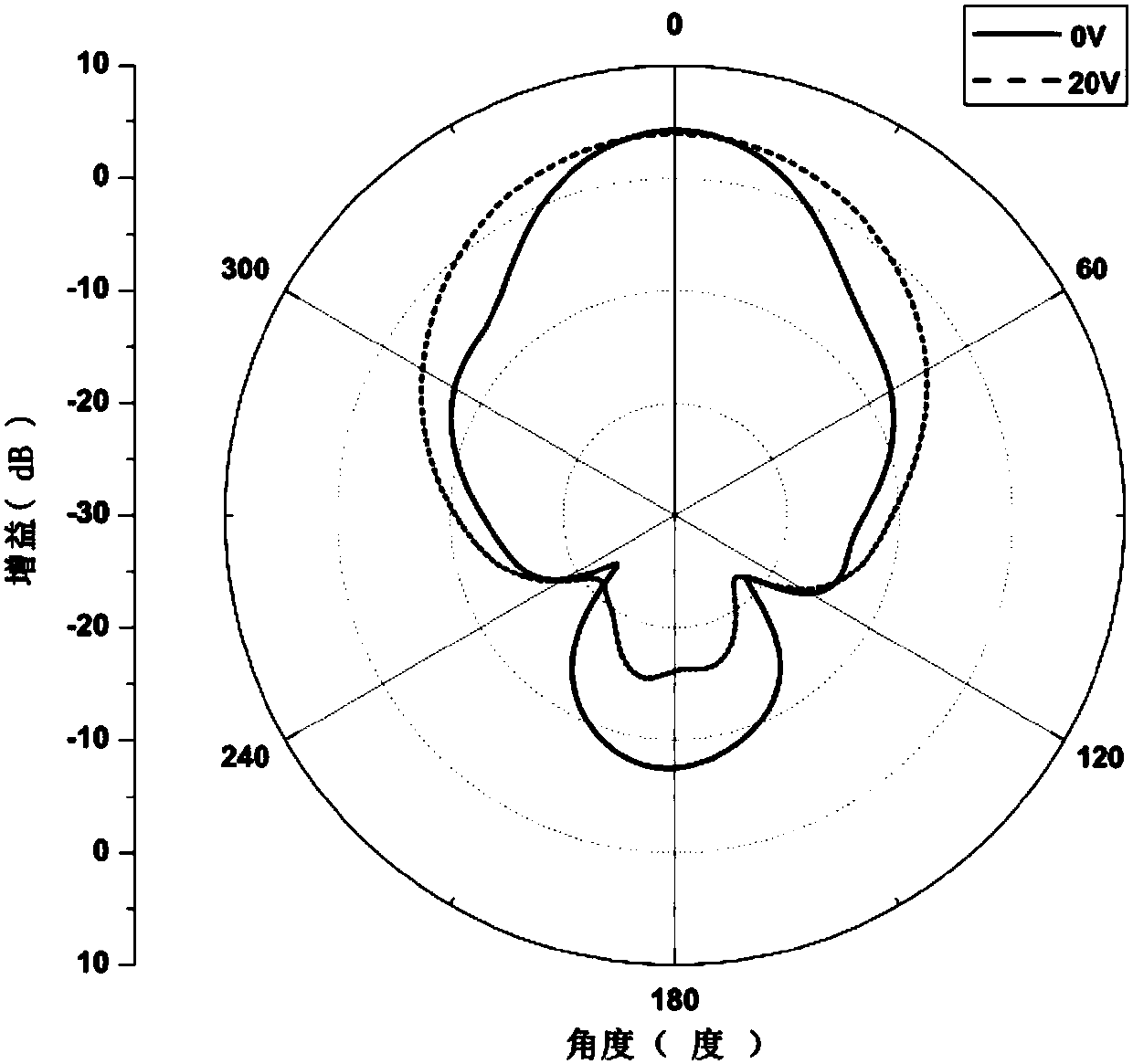
[0037] This embodiment is preferably as follows on the basis of the above embodiments: add a DC voltage to both ends of the liquid crystal material, and the DC voltage is loaded by the T-shaped biaser through the metal through hole on the medium below the active patch, that is, the two ends of the liquid crystal material, Changing the voltage of the DC bias circuit can change the effective dielectric constant of the liquid crystal material, thereby changing the operating frequency of the Yagi antenna. When it is necessary to change the working frequency of the Yagi antenna, it is only necessary to change the voltage of the DC bias circuit, and the operation is more convenient and simple.


PUM


Abstract

The invention discloses a frequency-reconfigurable microstrip patch yagi antenna, which comprises a three-layer structure. The first layer of the three-layer structure comprises a first dielectric substrate. A coupling microstrip line, a direct current bias circuit and a metal through hole are arranged on the upper surface of the first dielectric substrate. An impedance conversion line, a reflection patch, an active patch and a director patch are arranged on the lower surface of the first dielectric substrate. The reconstruction method of the yagi antenna is as follows: a direct-current voltage is added across the two ends of the liquid crystal material, and the direct-current voltage is loaded on a medium below the active patch through the metal through hole via a T-shaped bias device. Inthis way, the effective dielectric constant of the liquid crystal material can be changed by changing the voltage of the direct current bias circuit, and then the working frequency of the yagi antenna is changed. According to the scheme, the antenna and the method are adopted, and the frequency reconstruction of the antenna is convenient. The reconstructed antenna is easy to integrate, and the processing difficulty of the antenna is reduced. Meanwhile, a main lobe beam can be concentrated between the side shooting direction and the end shooting direction, and the signal receiving effect is better.

Description

technical field [0001] The invention relates to the field of microwave technology, in particular to a frequency reconfigurable microstrip patch Yagi antenna and a reconfiguration method. Background technique [0002] Most of the existing reconfigurable antennas use PIN diodes and varactor diodes as control means, but the electrical control means for the electromagnetic waves inside the antenna are not limited to the two forms of PIN diodes and varactor diodes. For different types of electrical control methods, the maturity, applicability, performance and other features (compatibility, difficulty of integration and feeding network, and operating frequency, etc.) considerations. [0003] PIN diodes and varactor diodes are lumped electrical tuning components, which can be easily embedded in the antenna structure itself due to their integration characteristics. Since the research on the principles and characteristics of this type of components is relatively mature and "plug an...

Claims


Application Information

Patent Timeline
Patent Type & Authority Applications(China)
IPC IPC(8): H01Q23/00H01Q19/30H01Q1/48H01Q1/50
CPCH01Q1/48H01Q1/50H01Q19/30H01Q23/00
Inventor 何子远刘雅玲杨伟胡晧全陈波唐璞张哲冯梅包永芳汪相如
Owner UNIV OF ELECTRONICS SCI & TECH OF CHINA
Why Eureka
Try Eureka