Energy balanced control method and device for energy-storage power supply system and balanced system

A technology of energy balancing and energy storage power supply, which is applied in the direction of circuit devices, charge balancing circuits, battery circuit devices, etc., can solve the problems of reducing operation and maintenance efficiency, not getting enough automatic balancing time, energy shrinkage, etc., to achieve detection and control Effects in simple steps

Inactive Publication Date: 2018-03-09
CHINA AVIATION LITHIUM BATTERY LUOYANG +1
View PDF11 Cites 3 Cited by
  • Summary
  • Abstract
  • Description
  • Claims
  • Application Information

AI Technical Summary

Problems solved by technology

However, the branch output architecture of conventional energy storage systems does not have any form of energy management and control components, and only relies on automatic energy balance between parallel battery packs
With the passage of system running time, the internal resistance of each branch is different. Although the external voltage of each branch is consistent during operation, the actual stored electric energy of each branch has been different. For such differences, as long as The system can recover automatically after a long enough rest time. However, as large-scale energy storage has higher and higher

Method used


Image

  • Energy balanced control method and device for energy-storage power supply system and balanced system
  • Energy balanced control method and device for energy-storage power supply system and balanced system
  • Energy balanced control method and device for energy-storage power supply system and balanced system

Examples


Embodiment Construction

[0045] The present invention will be described in further detail below in conjunction with the accompanying drawings.

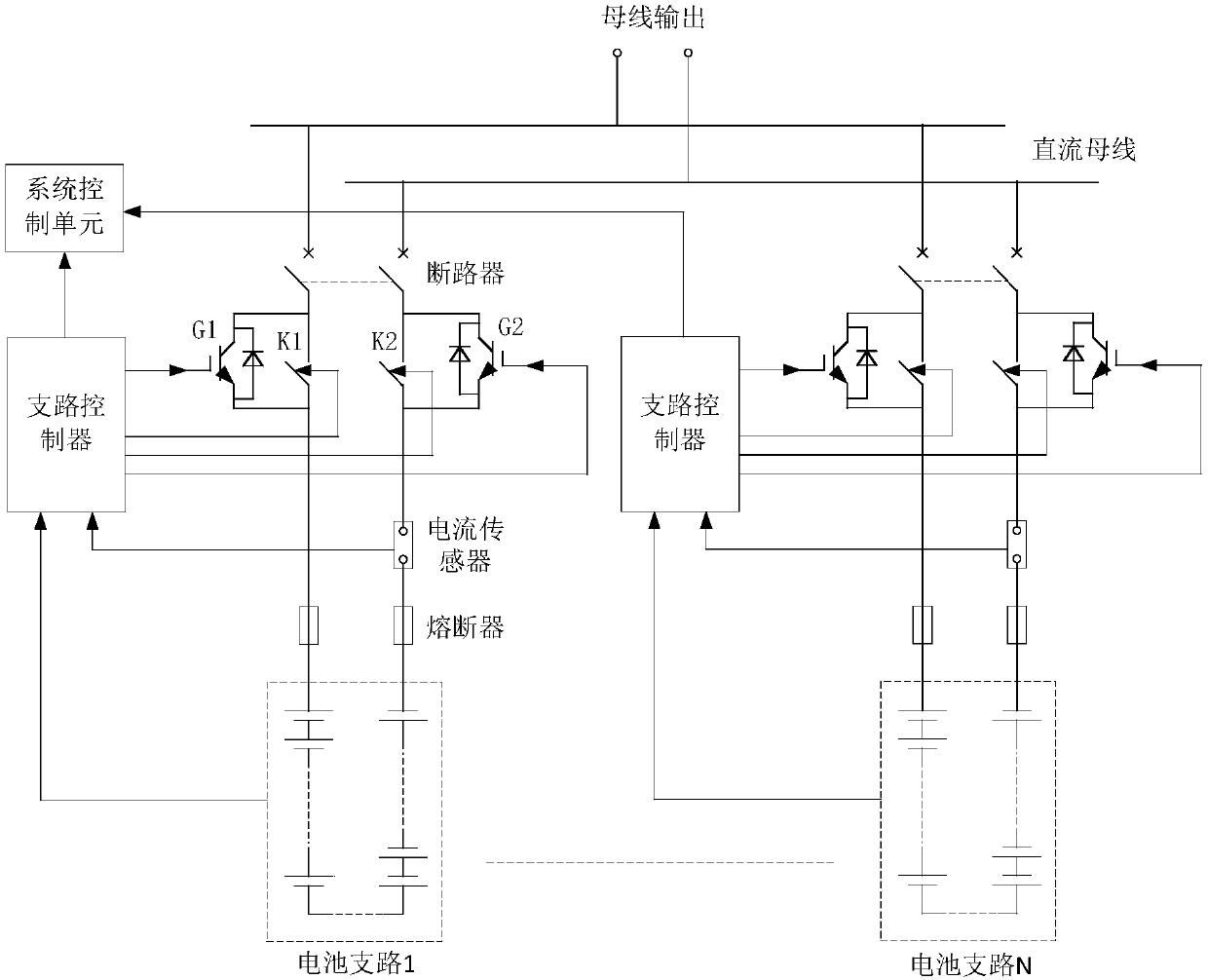
[0046] figure 1 It is the circuit diagram of the energy balance system of the energy storage power system. The system includes a battery pack, a power electronic switch, a bypass switch and a controller, wherein the battery pack includes N energy storage modules arranged in parallel, and each energy storage module consists of at least one single battery According to the corresponding connection relationship, N≥2. The part where each energy storage module is located is called an energy storage branch or a battery branch (hereinafter referred to as a battery branch). Therefore, in this embodiment, the system includes N battery branches.

[0047] Therefore, if figure 1 As shown, for any battery branch circuit, the branch circuit includes energy storage modules, fuses, current sensors and circuit breakers, and the connection relationship is as follows figure 1...


PUM


Abstract

The invention relates to an energy balanced control method and device for an energy-storage power supply system and a balanced system. The method comprises the following steps: during charging balanced control, acquiring actually stored electric energy of each energy storage module, and finding the minimal electric energy; calculating an error value between each of the other electric energy and the minimal electric energy, and judging the amplitude of each of the error values and a first set balanced threshold value, wherein for each of the error values exceeding the first set balanced threshold value, corresponding energy storage branches are controlled to perform charging according to corresponding PWM (Pulse-Width Modulation) control pulses; and during discharging balanced control, finding the maximal electric energy, and calculating an error value between the maximal electric energy and each of the other actual electric energy, wherein for each of the error values exceeding a second set balanced threshold value, corresponding energy storage branches are controlled to perform discharging according to the corresponding PWM control pulses. In the previous two situations, duty ratios of the PWM control pulses are in reverse proportion to the error values. Corresponding charging and discharging energy distribution is performed according to the energy state of each energy storagemodule, so that energy balanced control is realized.

Description

technical field [0001] The invention relates to an energy balance control method, a control device and a balance system of an energy storage power supply system, and belongs to the technical field of energy balance control of an energy storage power supply system. Background technique [0002] With the rapid development of the national new energy industry and smart grid construction, the application of large-scale energy storage systems is becoming more and more extensive. Limited by the structure of the PCS and the size of the DC bus voltage, the current energy storage power system generally uses multi-branch Parallel connection is used to meet the capacity and power requirements of the application scenario. According to the different topological structures of the DC side modules of the PCS, the access forms of the branches of the energy storage system are divided into two methods: centralized confluence access and sub-module access. Among them, the sub-module connection fo...

Claims


Application Information

Patent Timeline
IPC IPC(8): H02J7/00H02J1/10H02J1/14
CPCH02J1/10H02J1/14H02J7/0016H02J7/0019
Inventor 王子绩张瑞臧思佳谈作伟王佳斌
Owner CHINA AVIATION LITHIUM BATTERY LUOYANG
Why Eureka
Try Eureka