Staged flow constraining debris flow drainage slot and application thereof

A debris flow and drainage channel technology, which is applied in water conservancy projects, artificial waterways, embankments, etc., can solve the problems of reducing the movement speed of debris flow and cannot effectively reduce the flow energy of debris flow, so as to reduce the movement speed, increase protection efficiency, and enhance turbulence. Use the effect

Active Publication Date: 2018-03-16
INST OF MOUNTAIN HAZARDS & ENVIRONMENT CHINESE ACADEMY OF SCI
View PDF8 Cites 3 Cited by
  • Summary
  • Abstract
  • Description
  • Claims
  • Application Information

AI Technical Summary

Problems solved by technology

Although the traditional rectangular trough and V-shaped trough have no transverse ribs in the trough body, the local structure of the trough body is not easily damaged by debris flow, but this type of

Method used


Image

  • Staged flow constraining debris flow drainage slot and application thereof
  • Staged flow constraining debris flow drainage slot and application thereof
  • Staged flow constraining debris flow drainage slot and application thereof

Examples


Embodiment 1

[0023] Such as figure 1 , figure 2 , image 3 , Figure 4 shown. The drainage area of ​​a debris flow is 0.65km 2 , Debris flow ditch bed longitudinal gradient i 0 15% at P 2% Under the design standard, the flow of debris flow is 60m 3 / s, it is planned to build a debris flow drainage channel for protection. Due to the large slope of the channel, the debris flow will generally not be deposited in the drainage channel when it is released. On the contrary, due to the high kinetic energy of the debris flow, when it reaches the downstream protection area, it will cause serious damage. One of the important functions of building the drainage channel is to consume part of the kinetic energy in the debris flow, reduce the velocity of the debris flow, and reduce the damage of the debris fluid to the downstream. Therefore, the stage beam type debris flow drainage channel of the present invention is adopted.

[0024] The beam-type debris flow drainage trough of the stage include...

Embodiment 2

[0026] Such as figure 1 , figure 2 , image 3 , Figure 4 shown. A debris flow basin area of ​​6.0km 2 , Debris flow ditch bed longitudinal gradient i 0 30% at P 2% Under the design standard, the flow of debris flow is 200m 3 / s, it is planned to build the stage beam type debris flow drainage channel of the present invention along the debris flow channel for protection.

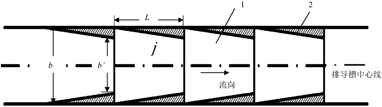
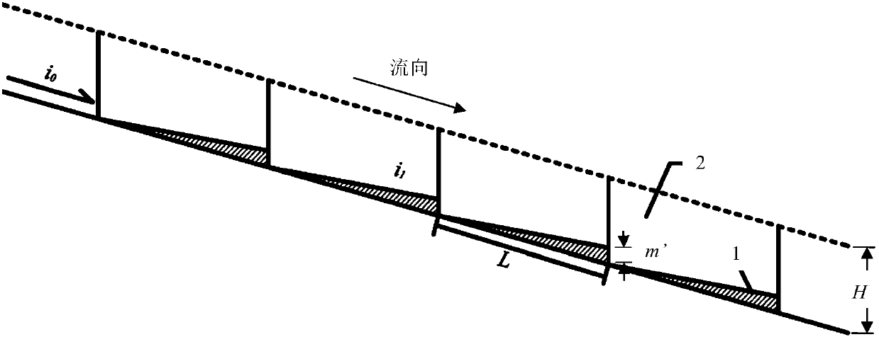
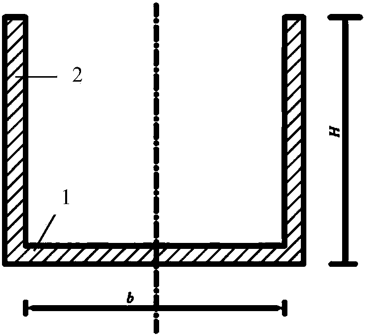
[0027]The beam-type debris flow drainage trough of the stage includes 20 sections of beam structures connected end to end; The flow section is exactly the same; the beam structure includes the bottom 1 of the tank and the side walls 2 on both sides. The bottom 1 of the tank gradually rises along the flow direction of the debris flow, and the side walls 2 on both sides gradually narrow toward the center line of the drainage channel along the flow direction of the debris flow. Tank bottom 1 vertical slope i 1 is 20%, the lifting rate of the tank bottom 1 is 0.063; the shrinkage width of the side wall ...


PUM


Abstract

The invention discloses a staged flow constraining debris flow drainage slot and an application thereof. The staged flow constraining debris flow drainage slot comprises a plurality of sections of flow constraining structural bodies connected end to end; the cross sections of passage at the inlet of the debris flow of the sections of flow constraining structural bodies are totally same, and the cross sections of passage at the outlet of the debris flow of the sections of flow constraining structural bodies are totally same; each of the flow constraining structural bodies comprises a slot bottom and side walls on two sides of the slot bottom, the slot bottom is gradually lifted along the flow direction of the debris flow and the side walls on two sides are gradually narrowed toward the center line of the drainage slot along the flow direction of the debris flow. By means of a design of gradually contracting the cross sections of passage of the flow constraining structural bodies and suddenly expanding two sections of flow constraining structural bodies, the staged flow constraining debris flow drainage slot can enhance turbulent fluctuation of the debris flow effectively, increase the energy dissipated ratio of the debris flow and reduce the speed of the debris flow so as to alleviate the abrading and scouring degrees of the drainage slot, so that the drainage safety of the debris flow in the downstream region is protected effectively. The staged flow constraining debris flow drainage slot is particularly suitable for high gradient channels in alpine regions and debris flowbodies containing large particle boulders.

Description

technical field [0001] The invention relates to a mud-rock flow prevention technology, in particular to a stage-beam type mud-rock flow drainage guide groove suitable for a channel with a large gradient in a high mountain area and an application thereof. Background technique [0002] The geological structure is active in the high mountain area, the topographic height difference is huge, and the climate space is obviously different, so it is very easy to form large-scale debris flows. Due to the characteristics of large-scale debris flow with high velocity, high inertia, and strong impact and destructive force, high-speed debris flow often poses a serious threat to residential areas in downstream areas and national facilities such as communications, roads, and electricity. Therefore, it is necessary to have energy dissipation and anti-scour The structure and shape of the debris flow drainage channel can protect the lives and property of the people in the downstream area. [...

Claims


Application Information

Patent Timeline
IPC IPC(8): E02B5/00E02B3/10
CPCE02B3/10E02B5/00
Inventor 陈华勇柳金峰游勇陈晓清陈剑刚赵万玉唐金波
Owner INST OF MOUNTAIN HAZARDS & ENVIRONMENT CHINESE ACADEMY OF SCI
Why Eureka
Try Eureka