Check patentability & draft patents in minutes with Patsnap Eureka AI!

Circuit arrangement for monitoring a flyback diode

A technology of freewheeling diodes and circuit devices, which can be used in measuring devices, electronic circuit testing, measuring electricity, etc., can solve the problems of increasing total cost, high circuit overhead, high cost, etc., and achieve fast monitorability and improved realizability Effect

Active Publication Date: 2018-03-16
KNORR-BREMSE SYST FUER NUTZFAHRZEUGE GMBH
View PDF8 Cites 0 Cited by
  • Summary
  • Abstract
  • Description
  • Claims
  • Application Information

AI Technical Summary

Problems solved by technology

It is therefore disadvantageous not only the high circuit outlay on the analog side for realizing the valve current measurement, but also the high costs associated therewith, which undesirably increases the overall costs, especially with a large number of standard modules

Method used


Image

  • Circuit arrangement for monitoring a flyback diode
  • Circuit arrangement for monitoring a flyback diode

Examples


Embodiment Construction

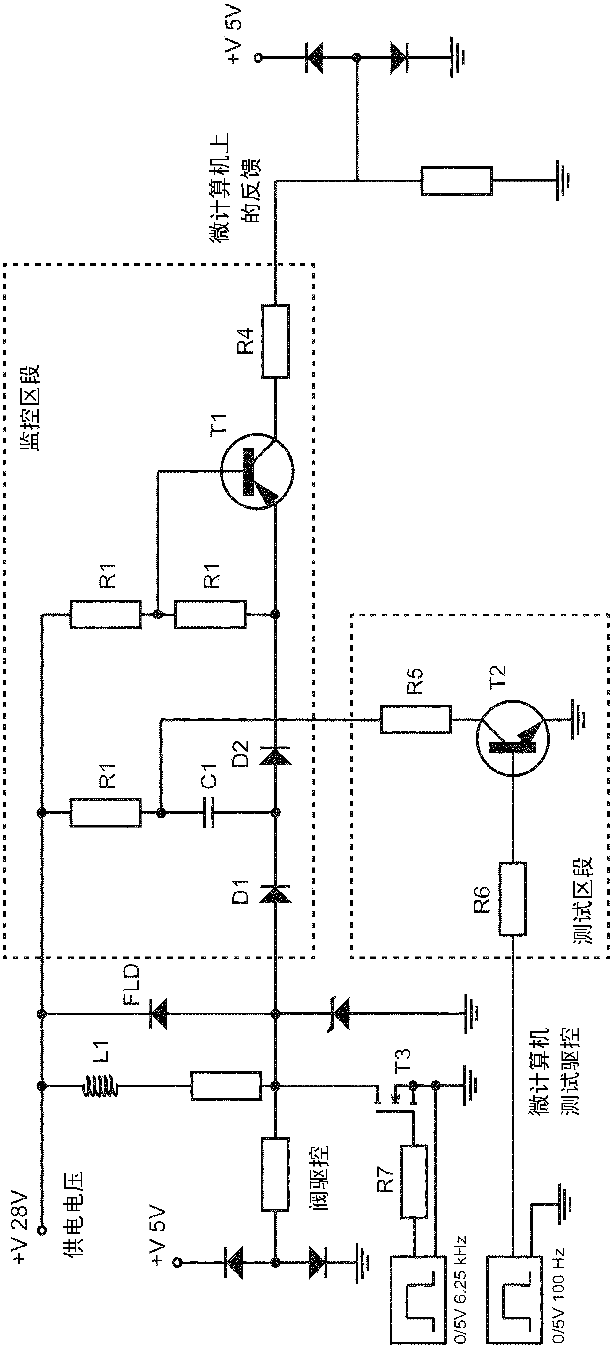
[0036] figure 1 A simplified schematic diagram according to a first exemplary embodiment of a circuit arrangement for monitoring a freewheeling diode on a solenoid valve actuated by pulse width modulation is shown. According to the embodiments described here, the circuit arrangement shown can be provided primarily for a solenoid valve drive stage in a central electronic control unit, which controls or regulates, especially for commercial use, via solenoid valves connected to stored air. Brake pressure in the wheel cylinders of the electro-pneumatic brakes of vehicles and / or commercial vehicles with trailers. However, it is not limited thereto. By means of the described circuit arrangement, it is also possible to monitor other freewheeling diodes.

[0037] like figure 1 As shown, the entire circuit arrangement contains a monitoring section (shown at the top in the drawing) and a test or inspection section (shown at the bottom in the drawing). In this respect, the monitoring...


PUM


Abstract

The invention relates to a circuit arrangement for monitoring a flyback diode on a magnetic valve, which is controlled by means of pulse width modulation, which circuit arrangement contains at least one diode (D1) in a pulse width modulation control branch of the circuit arrangement and a monitoring transistor (T1). The diode (D1) in the control branch is connected to the flyback diode (FLD) to bemonitored, arranged in the forward direction and, upon exceeding the threshold voltage thereof, activates the monitoring transistor (T1), which then outputs a monitoring signal. In a test mode, the monitoring transistor is periodically interconnected, independently of other states in the circuit arrangement, and a periodic monitoring signal is thus generated which is conducted to the same output.If a sustained, high-level monitoring signal is detected there, it is determined that the flyback diode (FLD) is faulty. If a periodically high-level and then abating monitoring signal is detected, it is determined that the flyback diode (FLD), a first partial circuit arrangement for monitoring the flyback diode (FLD), and a second partial circuit arrangement for testing the first partial circuitarrangement are working properly. If no signal is detected, a fault is determined in the partial circuit arrangements.

Description

technical field [0001] The invention relates to a circuit arrangement for monitoring a diode, in particular to a circuit arrangement for monitoring a freewheeling diode on a solenoid valve actuated by means of PWM. Background technique [0002] Freewheeling diodes are often used to protect against overvoltage when switching off inductive DC voltage loads in solenoid valves. For this purpose, a semiconductor diode is connected in parallel with the magnet as an inductive DC load, so that it is required by the supply voltage in the blocking direction. After switching off the supply voltage, the self-induction of the coil causes the current to continue to flow first in the original direction. Without freewheeling diodes, this leads to voltage peaks which are superimposed on the operating voltage and can damage or destroy the switching path. However, the voltage peaks are limited to the conduction voltage of the diode by means of the freewheeling diode, so that the electronic c...

Claims


Application Information

Patent Timeline
IPC IPC(8): G01R31/28
CPCG01R31/2829
Inventor T·福伊希特
Owner KNORR-BREMSE SYST FUER NUTZFAHRZEUGE GMBH
Features
  • R&D
  • Intellectual Property
  • Life Sciences
  • Materials
  • Tech Scout
  • Unparalleled Data Quality
  • Higher Quality Content
  • 60% Fewer Hallucinations
Learn More