Complete rectifying device for regeneration of waste oil

A technology for regeneration of waste oil and a complete set of devices, which is applied in the field of oil purifiers, can solve the problems of improving quality, single quality, high sulfur and impurities in oil, and achieves the effects of not easy scaling and damage, reducing production costs, and having a scientific and reasonable structure.

Pending Publication Date: 2018-03-20
CHONGQING FANGSHENG CLEANING EQUIP CO LTD
View PDF8 Cites 1 Cited by
  • Summary
  • Abstract
  • Description
  • Claims
  • Application Information

AI Technical Summary

Problems solved by technology

[0003] The company has applied for the "Waste Oil Cracking and Distillation Regeneration System", the patent application number is 2015102771925. This technical solution integrates the gasification separation process and the distillation treatment process, and combines the cracking and rectification of waste oil into one First, continuous production can be carried out, and the catalyst does not need to be replaced for many years, which significantly improves the dehydration, degassing, decolorization, desulfurization, cracking, and rectification effects of waste oil. However, in production practice, we found that the existing waste oil pyrolysis There are three major deficiencies in the distillation regeneration system: first, when the horizontal electric heating tube is heated at high temperature, the outer wall of the electric heating tube is very easy to scale, and the electric heating tube is also very easy to be damaged; second, the waste oil pyrolysis rectification regeneration system It is difficult to control the temperature and vacuum degree, and the quality of the regenerated oil is single, and the type of oil cannot be adjusted and controlled at will; the third is that the oil separated from the gas-liquid separation tower to the oil storage tank contains high sulfur and impurities, and the quality needs to be further improved

Method used


Image

  • Complete rectifying device for regeneration of waste oil
  • Complete rectifying device for regeneration of waste oil
  • Complete rectifying device for regeneration of waste oil

Examples


Embodiment 1

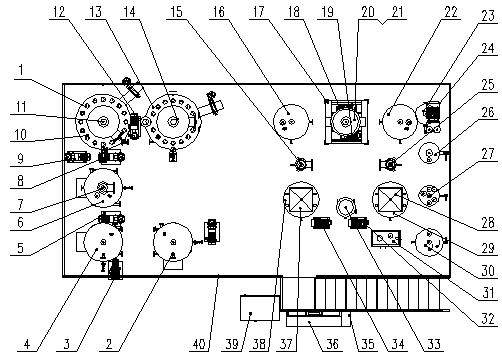
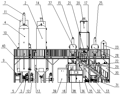
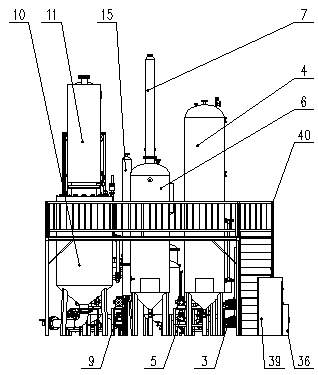
[0033] refer to figure 1 , figure 2 , image 3 , Figure 4 , Figure 5 , a complete set of waste oil regeneration and rectification equipment, on the ground and on the equipment mounting frame 40, a pretreatment tank, a reaction kettle 6, a fractionation tower 7, a distillation tower 10, a catalytic tower 11, a reboiler tower 13, and a refining tower are installed in an orderly manner. Distillation tower 14, cooling tower 20, gas-liquid separator 21, semi-finished product tank, desulfurization tower, light oil storage tank 23, distillation vacuum pump unit 24, filter vacuum pump unit 31, steam-water separator 26, buffer tank 27, filter tank, isolation Cupping tank 30, oil spill tank 33, pneumatic valve box 35, console 36, power cabinet 39 are connected in order with pipe fittings, oil pump, electric wire, in described reactor 6, distillation tower 10, catalytic tower 11, again The boiling tower 13 and the rectifying tower 14 are provided with a vertical electric heating t...

Embodiment 2

[0035] refer to figure 1 , figure 2 , image 3 , Figure 4 , Figure 5 , a complete set of waste oil regeneration and rectification equipment, on the ground and on the equipment mounting frame 40, a pretreatment tank, a reaction kettle 6, a fractionation tower 7, a distillation tower 10, a catalytic tower 11, a reboiler tower 13, and a refining tower are installed in an orderly manner. Distillation tower 14, cooling tower 20, gas-liquid separator 21, semi-finished product tank, desulfurization tower, light oil storage tank 23, distillation vacuum pump unit 24, filter vacuum pump unit 31, steam-water separator 26, buffer tank 27, filter tank, isolation Cupping tank 30, oil spill tank 33, pneumatic valve box 35, console 36, power cabinet 39 are connected in order with pipe fittings, oil pump, electric wire, in described reactor 6, distillation tower 10, catalytic tower 11, again The boiling tower 13 and the rectifying tower 14 are provided with a vertical electric heating t...

Embodiment 3

[0037] refer to figure 1 , figure 2 , image 3 , Figure 4 , Figure 5 , a complete set of waste oil regeneration and rectification equipment, on the ground and on the equipment mounting frame 40, a pretreatment tank, a reaction kettle 6, a fractionation tower 7, a distillation tower 10, a catalytic tower 11, a reboiler tower 13, and a refining tower are installed in an orderly manner. Distillation tower 14, cooling tower 20, gas-liquid separator 21, semi-finished product tank, desulfurization tower, light oil storage tank 23, distillation vacuum pump unit 24, filter vacuum pump unit 31, steam-water separator 26, buffer tank 27, filter tank, isolation Cupping tank 30, oil spill tank 33, pneumatic valve box 35, console 36, power cabinet 39 are connected in order with pipe fittings, oil pump, electric wire, in described reactor 6, distillation tower 10, catalytic tower 11, again The boiling tower 13 and the rectifying tower 14 are provided with a vertical electric heating t...


PUM


Abstract

The invention provides a complete rectifying device for regeneration of waste oil, and relates to an oil purifier. According to the complete rectifying device for regeneration of the waste oil, a pretreatment tank, a reaction kettle, a fractionating tower, a distillation tower, a catalytic tower, a reboiling tower, a rectifying tower, a cooling tower, a gas-liquid separator, a semi-finished product tank, a desulfurizing tower, a light oil storage tank, a distillation vacuum pump unit, a filtration vacuum pump unit, a steam-water separator, a buffer tank, a filter tank, a fire isolating tank, an oil spill tank, a pneumatic valve box, a console and a power cabinet are sequentially installed on the ground and a mounting rack of the device, wherein vertical electric heating tubes are arrangedin the reaction kettle, the distillation tower, the catalytic tower, the reboiling tower and the rectifying tower. The device has a scientific and reasonable structure, and the defects in an existingpyrolysis rectifying system for regeneration of the waste oil can be overcome; the vertical electric heating tubes do not scale and get damaged easily, so that types of oil are adjusted and controlledat will, the effect of distillation of the waste oil is improved significantly, and the production cost of waste oil regeneration is reduced; therefore, the device has a promotion value.

Description

technical field [0001] The invention relates to an oil purifier, and more specifically relates to a waste oil regeneration and rectification complete set. Background technique [0002] Waste oil means that after the oil has been used for a period of time, due to the immersion of pollution impurities and the oxidative deterioration of some components, the oil that cannot be used and replaced is collectively referred to as waste oil. According to national regulations, waste oil is a hazardous waste. Purification and regeneration of waste oil can approach or meet the standards of new oil. It can also regenerate waste oil into fuel oil or base oil, turning waste into treasure and benefiting the country and the people. At present, there are mainly five kinds of waste oil regeneration processes: acid-base refining method, filter and sieve separation method, centrifugal separation method, gasification separation method, and distillation hydrofining method. Each process and equipmen...

Claims


Application Information

Patent Timeline
Patent Type & Authority Applications(China)
IPC IPC(8): C10G55/02
CPCC10G55/02
Inventor 豆远奎周强李彦明李良军
Owner CHONGQING FANGSHENG CLEANING EQUIP CO LTD
Why Eureka
Try Eureka