Drop tower frictional wear testing device and method

A friction and wear test, drop tower technology, applied in the direction of measuring devices, mechanical devices, testing wear resistance, etc., can solve the problems of ground simulation of complex trajectory three-dimensional movement, limited practical scope of research, friction and wear is blank, etc. , to achieve the effect of simple structure, strong impact resistance and precise loading

Pending Publication Date: 2018-03-20
SOUTH CHINA UNIV OF TECH
View PDF5 Cites 8 Cited by
  • Summary
  • Abstract
  • Description
  • Claims
  • Application Information

AI Technical Summary

Problems solved by technology

Although the water flotation method, the hanging wire counterweight method, and the air flotation platform can simulate the microgravity environment for a long time, the authenticity is poor
Because the existing simulation test methods such as water tanks, suspensions, and air flotation are not only unable to solve the problem of ground simulation of three-dimensional motion with complex trajectories, but also due to factors such as the flexibility of ropes, friction resistance in equipment, and the inertia of large-mass mechanisms make them effective. sex is not ideal
The drop tower method and aircraft parabolic flight can more realistically simulate the microgravity environment, but the cost of aircraft parabolic flight is high, and the practical scope for institutional research is limited
However, the microgravity time formed by the drop tower method is short, and it must bear a large impact and be limited by the drop environment. At present, there is no special friction and wear testing machine designed for the drop tower experiment in China. The friction and wear under is still in the blank

Method used


Image

  • Drop tower frictional wear testing device and method
  • Drop tower frictional wear testing device and method
  • Drop tower frictional wear testing device and method

Examples


Embodiment 1

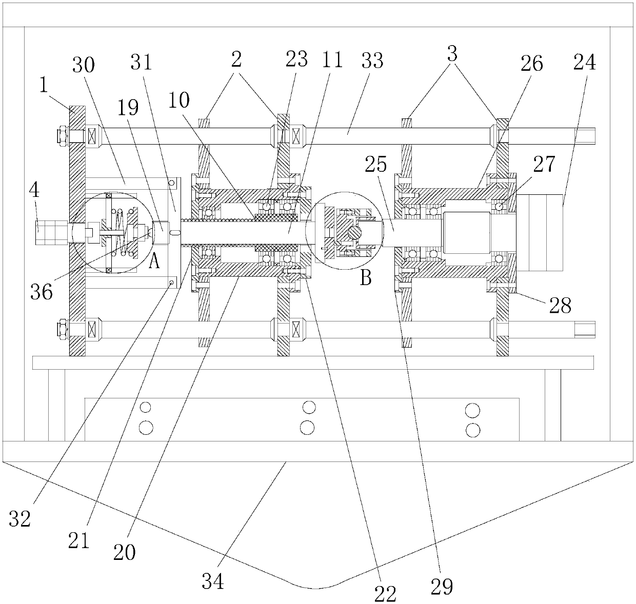
[0044] A drop tower friction and wear test device, comprising a load loading mechanism, a static sample clamping mechanism, a dynamic sample clamping mechanism, a friction power device and a frame fixedly installed in the drop tower drop chamber, the load loading mechanism, the static test The sample clamping mechanism, the dynamic sample clamping mechanism and the friction power device are arranged horizontally (horizontal) or vertically (vertical);

[0045] The frame consists of a load vertical plate, a sample fixture vertical plate and a power device vertical plate fixed in sequence. The load loading mechanism is fixed on the load vertical plate, and the static sample clamping mechanism is installed on the sample clamp vertical plate. The device is set on the power plant riser;

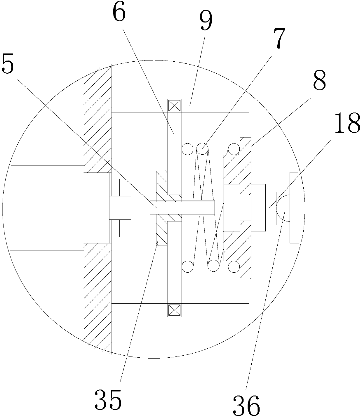
[0046] The load loading mechanism includes a stepper motor, a ball screw, a spring push plate, a loading spring, a spring mounting seat and a guide rail. The power output shaft of the step motor is...

Embodiment 2

[0062] This embodiment differs from Embodiment 1 in that:

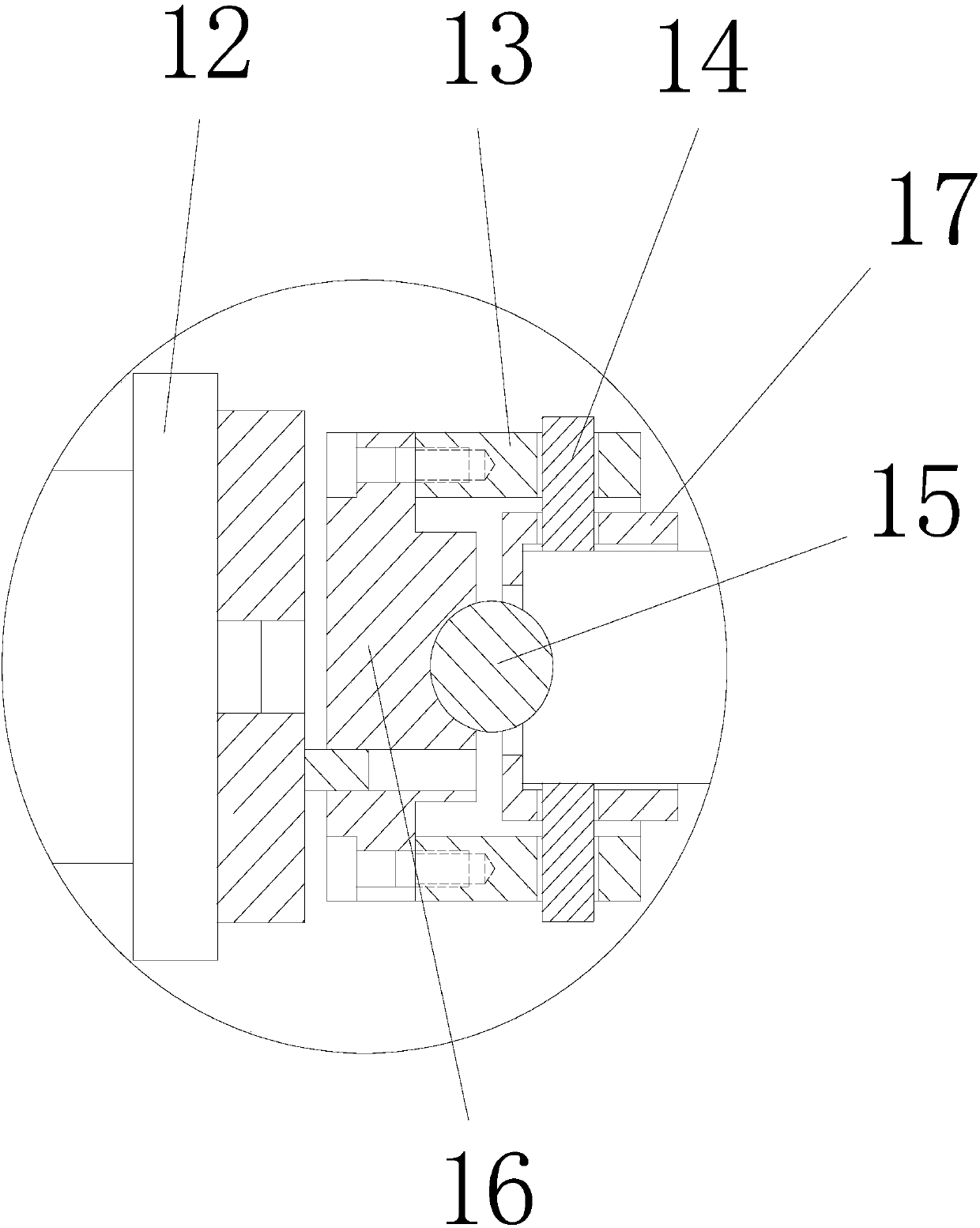
[0063] In this embodiment, a friction detection mechanism is also included. The friction detection mechanism includes a baffle, a transmission plate and a friction sensor, the baffle is fixedly arranged, the transmission plate is fixedly connected to the transmission shaft, and the static sample mounting seat is installed on the transmission shaft On the end face, the friction sensor is arranged on the baffle plate or the transmission plate and is located at the position where the baffle plate and the transmission plate are in contact during the test.

[0064] Here, the friction sensor is installed on the baffle plate as an example: During the test, the transmission shaft rotates to drive the drive plate to rotate toward the baffle plate (if the drive plate and the friction sensor are already in contact, the drive plate will move toward the baffle plate. Static pressure) so that the transmission plate is in contact wi...

Embodiment 3

[0066] In this embodiment, there are two friction sensors and two baffle plates, and the two baffle plates are fixedly arranged, and the two baffle plates are parallel, the middle part of the transmission plate is fixedly connected to the transmission shaft, and the two friction sensors are respectively arranged on The baffle plate is located at the position where the two ends of the transmission plate are in contact with the two baffle plates.

[0067] The friction data detected by the pressure sensor is collected by an instrument capable of collecting data at high speed, and the friction data is stored in the chip during the test. In order to meet the requirements of rapid detection and storage, the installation of two baffles is beneficial to reduce the vibration caused by impact during the experiment.


PUM


Abstract

The invention discloses a drop tower frictional wear testing device and method. The drop tower frictional wear testing device comprises a load loading mechanism, a static test sample clamping mechanism, a movable test sample clamping mechanism, a friction power device and a rack which is fixedly mounted in a drop cabin of a drop tower, wherein the load loading mechanism, the static test sample clamping mechanism, the movable test sample clamping mechanism and the friction power device are arranged in sequence. The drop tower frictional wear testing device has the advantages of simple structure, relatively high precision, stable structure and strong anti-impact capability; various index designs of the drop tower are completely referred and the device can be mounted in the drop cabin to carry out a micro-gravity drop tower frictional wear testing experiment; a micro-gravity environment can be relatively really simulated and influences, caused by micro-gravity, on frictional wear on the mechanism are explored; the blank of a mechanism frictional wear test under a current real micro-gravity environment is made up and influences, caused by the micro-gravity, on abrasion of a space mechanism are explored better.

Description

technical field [0001] The invention relates to the field of microgravity tribology, in particular to a drop tower friction and wear test device and method. Background technique [0002] Space agencies are mainly affected by environmental factors such as high vacuum, microgravity, alternating temperature, and radiation for a long time during their service in space. With the development of my country's aerospace industry, various space mechanisms are more and more used in space practice, and the research on the friction and wear of mechanisms in space environment is becoming more and more in-depth and extensive. However, the current research mainly focuses on high vacuum, In terms of environmental factors such as variable temperature and radiation, there are still few studies on the influence of microgravity on the friction and wear of moving mechanisms, and it is basically blank in China. [0003] To study the influence of microgravity on the wear of space mechanisms / moving ...

Claims


Application Information

Patent Timeline
Patent Type & Authority Applications(China)
IPC IPC(8): G01N3/56G01N3/04G01N3/06G01N19/02
CPCG01N3/04G01N3/06G01N3/56G01N19/02G01N2203/022G01N2203/005
Inventor 屈盛官段勇黄丽满李小强杨超
Owner SOUTH CHINA UNIV OF TECH
Why Eureka
Try Eureka