High voltage pulse thyristor switching device with thermal management

A high-voltage pulse and switching device technology, applied in thyristors, semiconductor devices, electric solid devices, etc., can solve the problems of large cooling system, small time scale, large energy consumption of cooling system, etc., to strengthen cooling effect and reduce heat conduction. Thermal resistance, the effect of increasing the heat exchange area

Active Publication Date: 2019-08-09
南京帕尔斯电气科技有限公司
View PDF6 Cites 0 Cited by
  • Summary
  • Abstract
  • Description
  • Claims
  • Application Information

AI Technical Summary

Problems solved by technology

In the pulse working mode, due to the small duration of the single pulse power of the thyristor, the heat is too late to be conducted from the thyristor to the evaporation section of the heat pipe through heat conduction, which will cause the junction temperature of the thyristor to rise instantaneously and lose control. Effective Thermal Management and Junction Temperature Control of Thyristors
[0005] Wan Heyong et al. (Wan Heyong, Li Xiaoguo. The main way to improve the heat dissipation effect of thyristors in high-power cabinets. Power Electronics Technology, 2002.4) proposed a technical measure for cooling high-power thyristors by means of air cooling, but this method is mainly aimed at constant and continuous The heat dissipation of the thyristors in the working state cannot solve the problem of heat accumulation under pulsed conditions, and brings about problems such as bulky cooling system and high energy consumption of the cooling system
[0006] In short, because the existing technology mainly designs the cooling system for the thermal characteristics of the switching device under continuous and stable working conditions, under the action of pulse power, the instantaneous heat generation of the device is too late to pass through the heat conduction method due to the small time scale of the single pulse power action Conducted to the cooling device, the instantaneous junction temperature of the device rises, which cannot meet the cooling requirements of the high-voltage pulse switching device, seriously affects the working performance and reliability of the high-voltage pulse thyristor switching device, and restricts the structure and working parameter design of the high-voltage pulse thyristor switching device

Method used


Image

  • High voltage pulse thyristor switching device with thermal management
  • High voltage pulse thyristor switching device with thermal management
  • High voltage pulse thyristor switching device with thermal management

Examples


Embodiment Construction

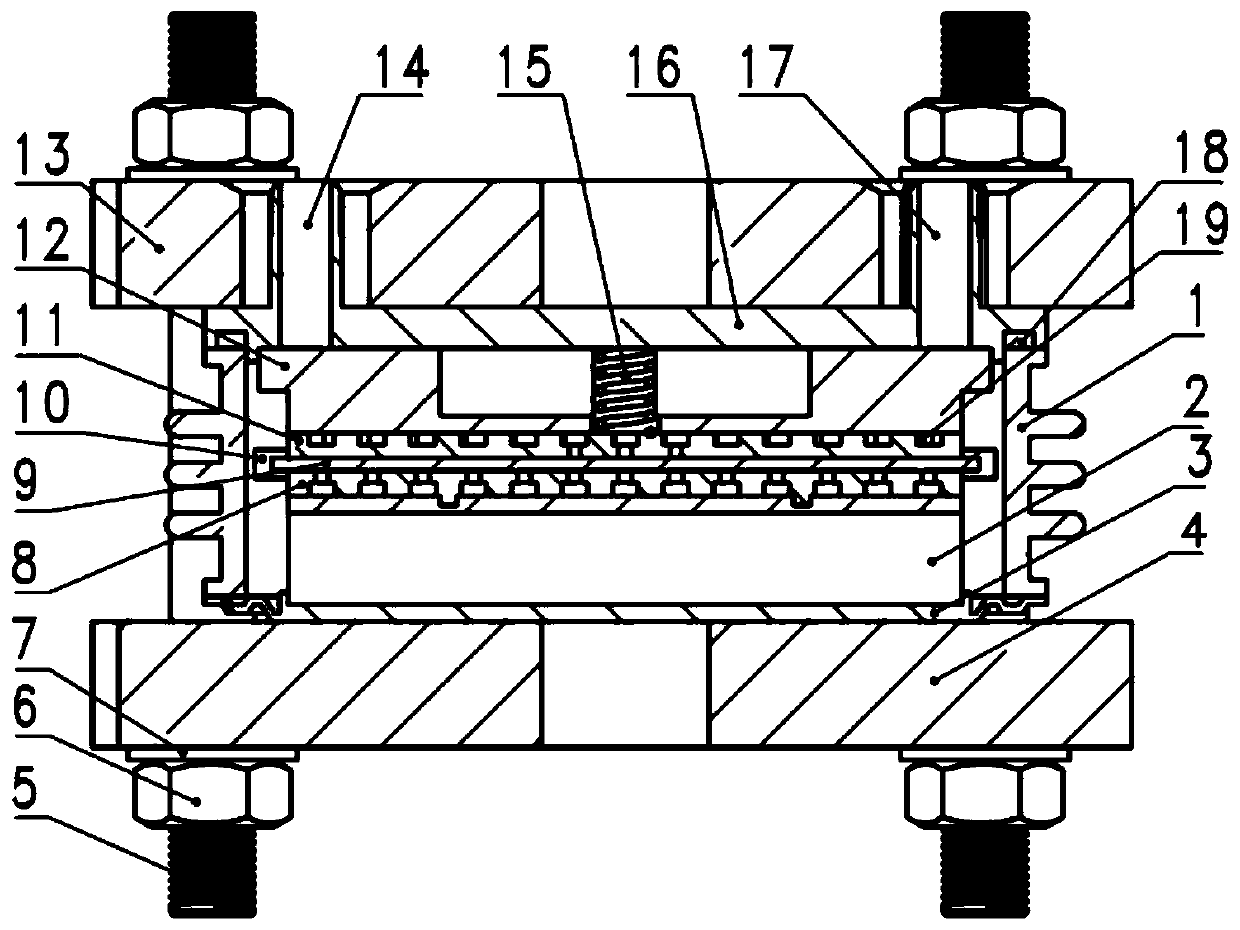
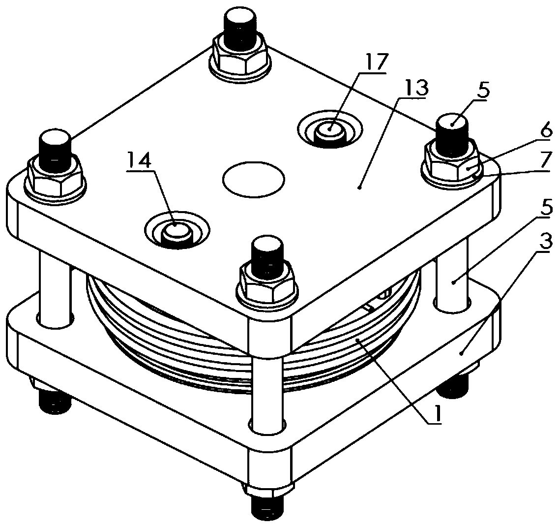
[0035] Such as figure 1 , 2 As shown, the high-voltage pulse thyristor switching device with heat management of the present invention includes a ceramic case 1 with a cylindrical inner cavity, a cathode base bottom plate 16 that is crimped and sealed on the upper end surface of the ceramic case 1 through a gasket 18, and a cathode base plate 16 that is sealed by welding The anode base bottom plate 3 sealed on the lower end surface of the ceramic shell 1;

[0036] It also includes an anode clamp 4 and a cathode clamp 13, the cathode clamp 13 is installed on the cathode base bottom plate 16, and the anode clamp 4 is installed under the anode base bottom plate 3; the cathode clamp 13 and the anode clamp 4 pass through the circumference Fasten and clamp the sealed cavity formed by the ceramic casing 1, the cathode base base plate 16 and the anode base base plate 3 to multiple groups of screw rods 5, nuts 6 and washers 7 that are uniformly arranged;

[0037] The anode heat dissip...


PUM


Abstract

The invention discloses a high-voltage pulse thyristor switching device with thermal management, which comprises a ceramic tube shell (1) with the inner cavity being cylindrical, a cathode base bottomplate (16) and an anode base bottom plate (3), and is characterized in that the a closed cavity formed by the ceramic tube shell (1), the cathode base bottom plate (16) and the anode base bottom plate (3) is filled with a cooling medium (19) and is directly contacted with an anode heat dissipation base (2), a first molybdenum clamping block (8), a silicon valve plate (9), an insulating sleeve (10), a second molybdenum clamping block (11), a cathode heat dissipation base (12) and a gate assembly (15) which are arranged in the closed cavity to perform heat exchange. The high-voltage pulse thyristor switching device with thermal management adapts to cooling requirements under the pulse power load, and is good in cooling effect, compact in structure of a cooling system and high in expansibility.

Description

technical field [0001] The invention belongs to the technical field of power electronics and pulse power source devices, in particular to a high-voltage pulse thyristor switching device with thermal management and good cooling effect and small volume. Background technique [0002] High-voltage pulse thyristor switching devices are the core components of pulse power systems. They are widely used for their powerful power levels and large overload capabilities, and have become the focus of continuous research in the field of pulse power technology. [0003] As the control link of the pulse power adjustment system, the working current of the high-voltage pulse thyristor switching device can be as high as hundreds of kiloamperes. The switching loss during the switching process and the ohmic loss during the conduction process will increase the junction temperature of the device, and the excessive The junction temperature will change the operating characteristics of the device and ...

Claims


Application Information

Patent Timeline
Patent Type & Authority Patents(China)
IPC IPC(8): H01L23/10H01L23/367H01L23/427H01L23/473H01L29/74
CPCH01L23/10H01L23/3672H01L23/427H01L23/473H01L29/74
Inventor 崔艳丽石晓晶
Owner 南京帕尔斯电气科技有限公司
Why Eureka
Try Eureka