Rotatable lifting device for construction engineering

A kind of construction engineering, rotary technology, applied in construction, building structure, processing of building materials, etc., can solve the problems of increasing the bearing load of the column, waste of resources, low flexibility, etc., to improve the structural stability and increase the operation. The effect of space and flexibility

Inactive Publication Date: 2018-03-23
MIANYANG MOSHI TECH CO LTD
View PDF1 Cites 17 Cited by
  • Summary
  • Abstract
  • Description
  • Claims
  • Application Information

AI Technical Summary

Problems solved by technology

[0002] During construction, a lot of building materials need to be moved. If the weight is heavy, it is usually lifted to the destination by a cantilever crane or bridge crane, while the weight is usually carried by a cart or manually. During this process, it is necessary to manually load and unload slowly, which requires a lot of manpower and time, which is not conducive to improving work efficiency, and it is easier to cause damage during manual loading and unloading. If the material with a small weight also uses a cantilever If the beam crane or bridge crane is used for hoisting, it will be overused, resulting in waste of resources, which is not conducive to energy saving and environmental protection
[0003] In the prior art, the patent application number CN201620774124.X discloses a rotary construction material handling device, including hydraulic rods, connecting rods, support rods, pillars, rotating discs, chassis and cover plates; the right end of the hydraulic rod It is fixedly connected with the left end of the rotating ring; the upper end of the pillar is provided with an annular groove, and the rotating ring is clamped on the annular groove of the pillar; the lower end of the pillar is fixedly connected with the center of the upper end of the rotating disk; The upper end is provided with a circular guide rail and a strip guide rail; the lower end of the connecting rod is arranged in the groove on the upper end of the cover plate through the rotating shaft; the left side of the lower end of the cover plate is fixedly connected with the upper end of the fixed top plate, and the lower end of the cover plate is provided with a moving guide rail ; The moving top plate is clamped in the moving guide rail; the left end of the fixed top plate is provided with a motor, and the right end of the fixed top plate is provided with a threaded screw and a guide rod; materials are clamped between the moving top plate and the fixed top plate; The technical solution realizes the automatic transportation of building materials and avoids the problem of high labor intensity of manual handling; however, the technical solution still has the following disadvantages: 1. The horizontal movement of the clamped building materials can only be realized through the hydraulic rod, while the hydraulic pressure While the length of the rod is elongated, the stress of the hydraulic rod is concentrated, and the moment borne by the pillar is also gradually increased, increasing the load of the column; 2. The flexibility is low, and it can only move and rotate in the horizontal direction, and it is impossible to carry the building materials to a higher level. 3. Since the clamping device for clamping building materials and the connecting rod are in a hinged setting, the building materials are prone to inertial shaking and instability during the transfer process, and the safety factor is low.

Method used


Image

  • Rotatable lifting device for construction engineering
  • Rotatable lifting device for construction engineering
  • Rotatable lifting device for construction engineering

Examples


Embodiment Construction

[0027] In order for those skilled in the art to better understand the present invention, the present invention will be further described in detail below in conjunction with the accompanying drawings and the following embodiments.

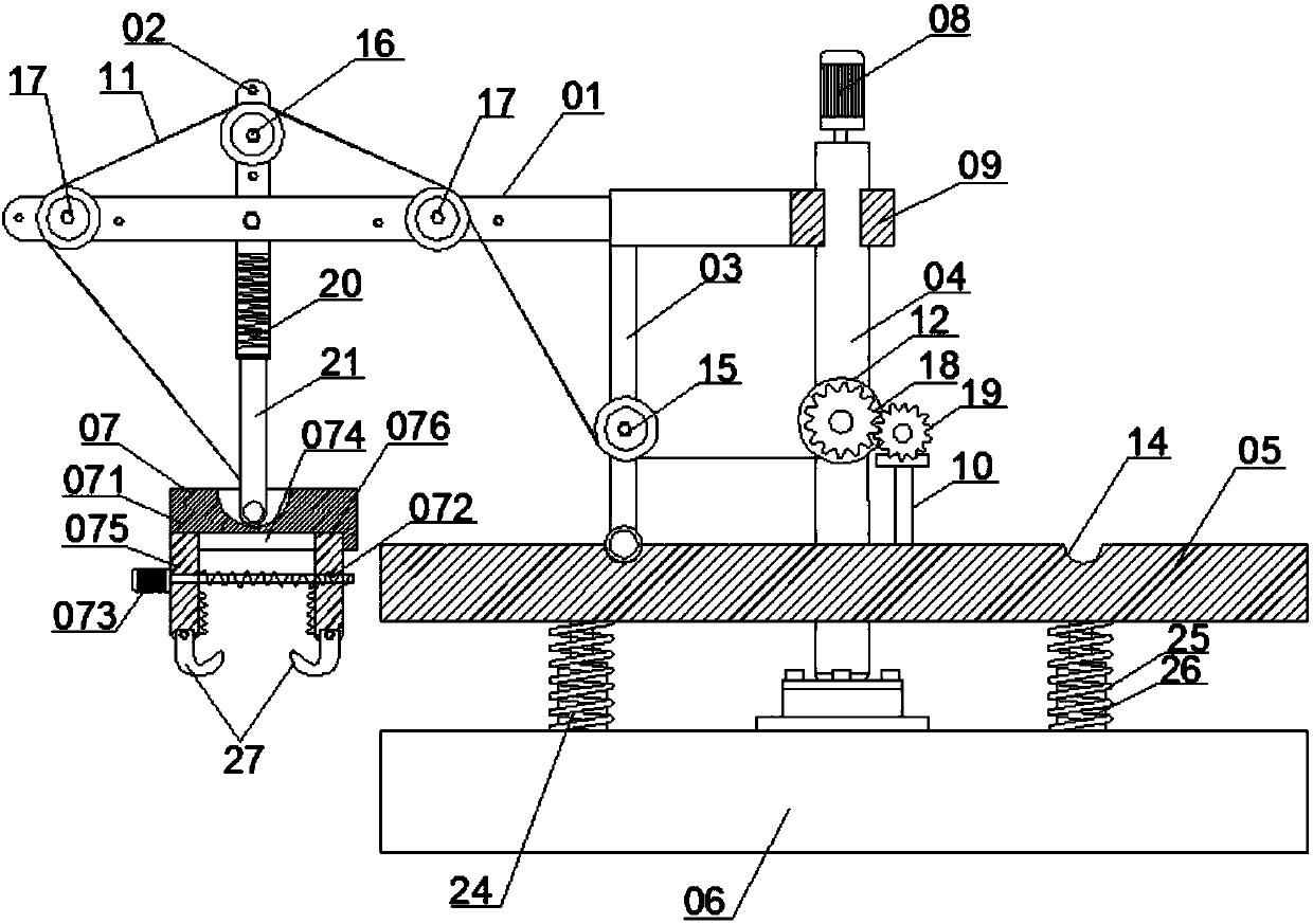
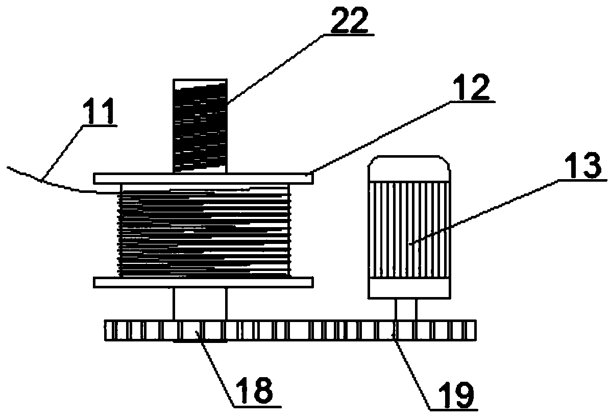
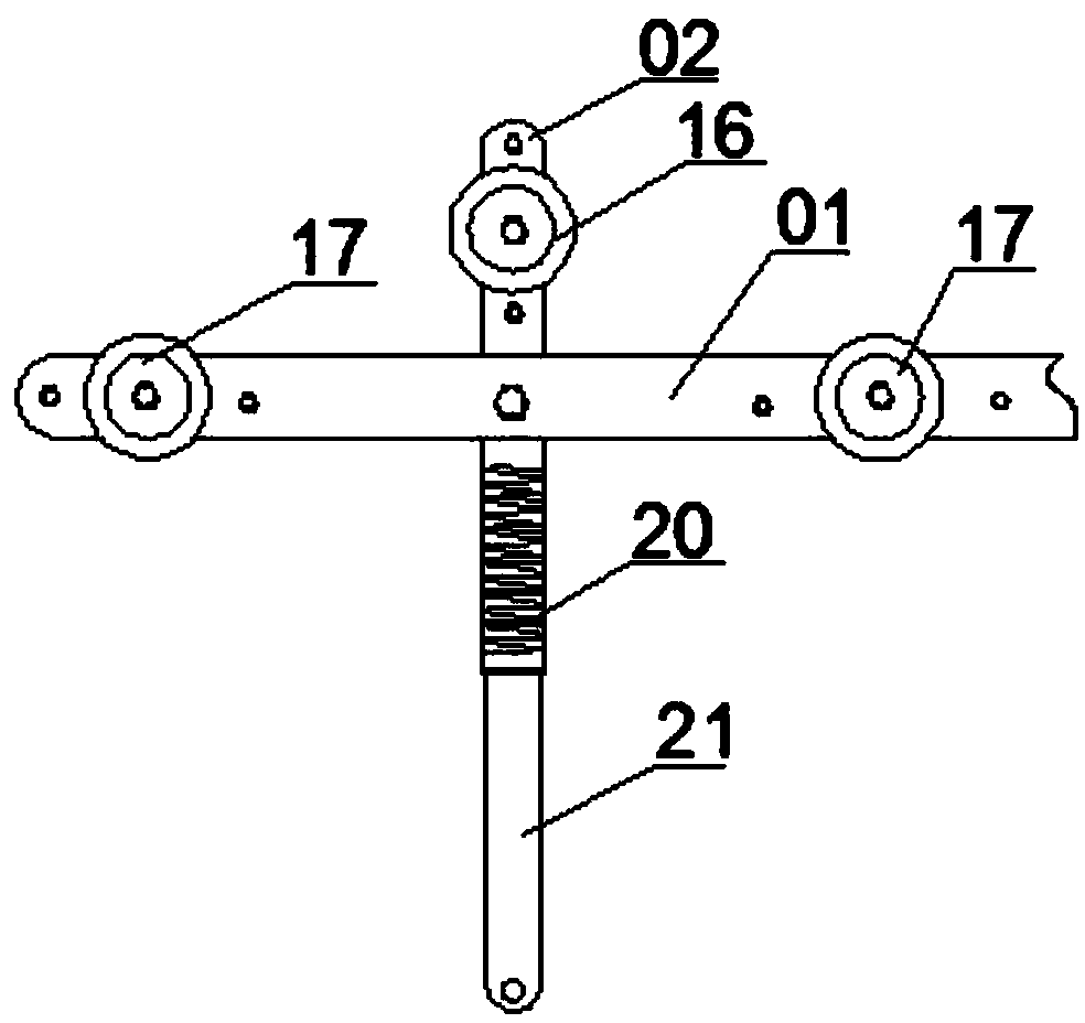
[0028] Please refer to Figure 1 to Figure 4 As shown, this embodiment provides a rotatable lifting device for construction engineering, including a hydraulic rod 01, a connecting rod 02, a support rod 03, a pillar 04, a rotating disc 05, a chassis 06 and a clamping device for clamping construction materials. Device 07, the clamping device 07 includes an connecting plate 071, a locking screw 072 and a micro stepping motor 073, the bottom of the connecting plate 071 is recessed inwardly and a moving guide rail 074 is provided, and the two ends of the moving guide rail 074 are correspondingly provided with a fixed plate 075 And the moving plate 076, the locking screw rod 072 is correspondingly installed between the fixed plate 075 and the moving plate...


PUM


Abstract

The invention discloses a rotatable lifting device for construction engineering, which relates to the technical field of construction industry equipment and aims to solve the problem in the prior art that a dangerous section of a hydraulic rod is easily broken due to stress concentration during the transfer process of building materials; it includes a hydraulic Rods, connecting rods, support rods, pillars, rotating discs, chassis and clamping devices for clamping construction materials, and also include lifting locking mechanisms, including pulley assemblies, wire ropes, winches, lead screws and for The driving assembly that drives the screw to rotate. The screw is fixedly connected to the winch and is threaded through the axis of the pillar vertically, and the rotation center line of the winch is perpendicular to the axis of the pillar. Tight on the winch. By implementing the technical solution, the gravity of the building material is dispersed at each stress point of the pulley assembly, avoiding the problem that the dangerous section of the hydraulic rod is easily broken due to stress concentration, and improving the safety factor.

Description

technical field [0001] The invention relates to the technical field of construction industry equipment, and more specifically relates to a rotatable lifting device for construction engineering. Background technique [0002] During construction, a lot of building materials need to be moved. If the weight is heavy, it is usually lifted to the destination by a cantilever crane or bridge crane, while the weight is usually carried by a cart or manually. During this process, it is necessary to manually load and unload slowly, which requires a lot of manpower and time, which is not conducive to improving work efficiency, and it is easier to cause damage during manual loading and unloading. If the material with a small weight also uses a cantilever If the beam crane or bridge crane is used for hoisting, it will be overused, resulting in waste of resources, which is not conducive to energy saving and environmental protection. [0003] In the prior art, the patent application number ...

Claims


Application Information

Patent Timeline
Patent Type & Authority Applications(China)
IPC IPC(8): B66C23/84B66C23/78B66C23/62E04G21/16
CPCB66C23/84B66C23/62B66C23/78E04G21/162
Inventor 赵平蒋旺林
Owner MIANYANG MOSHI TECH CO LTD
Why Eureka
Try Eureka