Multi-functional ultrasonic imaging system

An ultrasonic imaging system and multi-functional technology, applied in the field of circuits, can solve the problems of signal transmission channel signal instability, damage to the use effect of ultrasonic imaging, etc., and achieve the effect of great practical value and development value

Inactive Publication Date: 2018-03-23
XIDIAN UNIV +1
View PDF4 Cites 4 Cited by
  • Summary
  • Abstract
  • Description
  • Claims
  • Application Information

AI Technical Summary

Problems solved by technology

[0004] In view of the above situation, in order to overcome the defects of the prior art, the purpose of the present invention is to provide a multifunctional ultrasonic imaging system, which has the characteristics of ingenious design and humanized design, and effectively solves the problems caused by electromagnetic waves when the existing multifunctional ultrasonic imaging equipment is used. Interference, electromagnetic interference will make the signal of the signal transmission channel in the multifunctional ultrasonic imaging equipment unstable, and when the signal is too low, it will also generate static electricity, short circuit the circuit, and destroy the use effect of ultrasonic imaging

Method used


Image

  • Multi-functional ultrasonic imaging system
  • Multi-functional ultrasonic imaging system

Examples


Embodiment 1

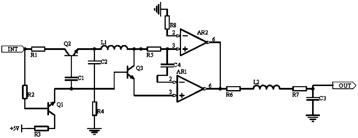
[0013] Embodiment 1, the multifunctional ultrasonic imaging system includes an oscillation frequency modulation circuit, a comparison circuit and a filter circuit, the oscillation frequency modulation circuit receives the input signal of the signal transmission channel of the multifunctional ultrasonic imaging system, and uses triodes Q1-Q3 to form a composite circuit for frequency selection, Then the comparison circuit uses the operational amplifier AR1 to amplify the signal and input it into the filter circuit. At the same time, the operational amplifier AR2 is designed to feed back the signal of the operational amplifier AR1 to stabilize the output signal of the operational amplifier AR1. The output signal of the operational amplifier AR1 passes through the inductor L2 The RC circuit connected in parallel with the series resistor R7 and the capacitor C3 is filtered and output, that is, it is input into the signal transmission channel of the multifunctional ultrasonic imaging ...

Embodiment 2

[0015] Embodiment 2, on the basis of Embodiment 1, the signal output by the comparison circuit contains clutter, so the inductance L2 is designed to filter out high-frequency clutter, and at the same time, an RC circuit filter with a resistor R7 and a capacitor C3 connected in parallel is connected in series, and the RC circuit The low-frequency clutter in the signal is filtered out, thus stabilizing the analog signal of the multi-functional ultrasonic imaging device, which is input into the signal transmission channel of the multi-functional ultrasonic imaging device, the other end of the resistor R6 is connected to one end of the inductor L2, and the other end of the inductor L2 is connected to the resistor One end of R7 and the other end of the resistor R7 are connected to one end of the capacitor C3, and the other end of the capacitor C3 is connected to the signal output port.

Embodiment 3

[0016] Embodiment 3, on the basis of Embodiment 2, the oscillating frequency modulation circuit uses the turn-on voltage of the triode Q1 to filter out signals with lower amplitudes of the input signal of the signal transmission channel of the multifunctional ultrasonic imaging system, that is, interference signals, The emitter potential of the transistor Q1 is the control electrode potential of the transistors Q3 and Q2, and the capacitor C1 acts as a filter, and the emitter potential of the transistor Q2 is filtered in parallel by the inductor L1 and the capacitor C2 and becomes the collector potential of the transistor Q3, so the transistor Q2 It can reduce the potential in the input signal of the signal transmission channel of the multifunctional ultrasonic imaging system, and at the same time, it can provide a stable collector potential for the triode Q3 through the parallel filtering of the inductance L1 and the capacitor C2. At this time, the conduction voltage of the tri...


PUM


Abstract

The invention discloses a multi-functional ultrasonic imaging system including an oscillation frequency modulation loop, a comparison circuit and a filter circuit. The oscillation frequency modulationloop receives an input signal of a signal transmission channel of the multi-functional ultrasonic imaging system and uses triodes Q1-Q3 to form a composite circuit for frequency selection. Then, thecomparison circuit uses the operational amplifier AR1 to amplify the signal to be input into the filter circuit. At the same time, an operational amplifier AR2 is designed to feed back the signal of the operational amplifier AR1, the output signal of the operational amplifier AR1 is stabilized, and the output signal of the operational amplifier AR1 is in series connection with an RC circuit via aninductor L2 for filtering and then is output, namely, is input in the signal transmission channel of the multi-functional ultrasonic imaging system, wherein a resistor R7 and a capacitor C3 in the RCcircuit are connected in parallel. The multi-functional ultrasonic imaging system has great practical and development value.

Description

technical field [0001] The invention relates to the technical field of circuits, in particular to a multifunctional ultrasonic imaging system. Background technique [0002] Multifunctional ultrasonic imaging equipment has important uses in medical treatment and navigation. Among them, the signal transmission of the signal transmission channel of multifunctional ultrasonic imaging equipment is susceptible to electromagnetic interference, and there are many sources of electromagnetic interference. Most electronic equipment will emit electromagnetic interference. Electromagnetic interference will make the signal of the signal transmission channel in the multifunctional ultrasonic imaging equipment unstable, and when the signal is too low, it will also generate static electricity, short circuit the circuit, and destroy the use effect of ultrasonic imaging. [0003] So the present invention provides a new solution to solve this problem. Contents of the invention [0004] In vi...

Claims


Application Information

Patent Timeline
Patent Type & Authority Applications(China)
IPC IPC(8): H03H11/12A61B8/00
CPCA61B8/00H03H11/1217
Inventor 李迪刘治勇费春龙杨银堂朱樟明李娅妮
Owner XIDIAN UNIV
Why Eureka
Try Eureka