Copying welding device free of blind area and copying welding method free of blind area

A welding device and a welding method technology are applied in the profiling non-blind zone welding device and the welding field thereof, which can solve the problems of complicated profiling welding, high functional cost, and inability to perform welding, and achieve low functional cost, strong aesthetics, Consistent appearance

Inactive Publication Date: 2018-03-27
HIMILE MECHANICAL MFG
View PDF0 Cites 6 Cited by
  • Summary
  • Abstract
  • Description
  • Claims
  • Application Information

AI Technical Summary

Problems solved by technology

However, since the welding trolley itself has a certain width, if there are obstacles on both sides of the weld seam length direction, welding cannot be performed at the beginning and end of the weld seam, and manual subsequent repair welding is required. The appearance is different, affecting the aesthetics
[0003] At present, the existing non-blind zone welding trolley is usually driven by two motors, and the linear swing of the welding torch head is realized through intelligent control. For arc welds, the welding speed and welding distance must be guaranteed, and the different arcs

Method used


Image

  • Copying welding device free of blind area and copying welding method free of blind area
  • Copying welding device free of blind area and copying welding method free of blind area
  • Copying welding device free of blind area and copying welding method free of blind area

Examples


Embodiment 1

[0059] Example 1 Profiling non-blind zone welding device

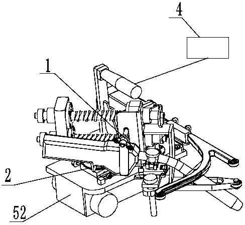
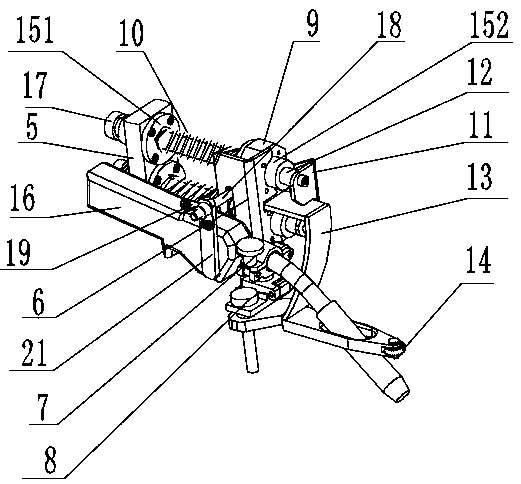
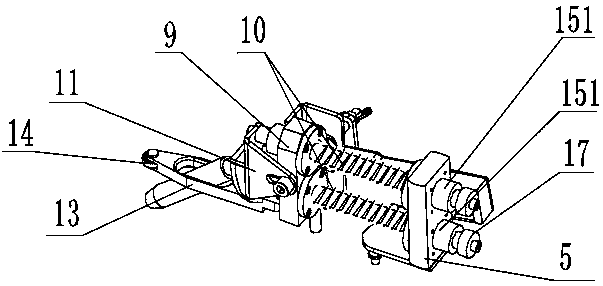
[0060] Such as Figure 1-14 As shown, the present invention provides a profiling non-blind spot welding device. The profiling non-blind spot welding device includes a welding gun profiling adjusting frame 1, a driving and transmission system 2, a base 52, and a control device 4.

[0061] The welding gun profiling adjusting frame 1 includes a rotating seat 5, an auxiliary welding torch clamp 6, a welding torch clamp 7, an adjusting seat 8, a fixing seat 9, a spring 10, a spring adjuster 11, a polished rod 12, a profiling wheel frame 13, and a profiling wheel 14. The first linear bearing 151, the second linear bearing 152, the welding gun 16, the gland 17, the bolt 18, and the wing nut 19.

[0062] The rotating base 5 is located at one end of the polished rod 12, and a light hole is opened on the rotating base 5, and the first linear bearing 151 is embedded in the light hole. The number of light holes is preferably two, and wh...

Embodiment 2

[0095] Example 2 Method of profiling welding without blind zone

[0096] Such as Figure 15-18 As shown, the present invention also provides a profiling method for welding without blind spots, which includes the following steps: a welding gun adjustment step, a welding gun straight-line welding step, and a base operating step;

[0097] among them:

[0098] Welding gun adjustment steps; put the profiling non-blind spot welding device on the workpiece to be welded, adjust the welding torch 16 to the side away from the side wheel 38, and to the limit stroke, so that the front wheel 29 leans against the front side of the workpiece 54, and the profiling wheel 14 Lean against the corner of the weld formed by the side 55 of the workpiece and the front 54 of the workpiece; at the same time, the torch linear welding step and the base operating step are started.

[0099] The welding torch is in a straight line welding step; the motor 36 is activated, and the coupling 35 and the worm 33 rotate t...

Embodiment 3

[0104] Example 3 Method for profiling welding without blind zone

[0105] Such as Figure 19-22 As shown, the present invention also provides a profiling welding method without blind spots. The difference from Embodiment 2 is that the welding method includes the following steps: a welding gun adjustment step, a welding gun arc welding step, and a base operation step;

[0106] among them:

[0107] Welding gun adjustment steps; put the profiling non-blind spot welding device on the workpiece to be welded, adjust the welding torch 16 to the side away from the side wheel 38, and to the limit stroke, so that the front wheel 29 leans against the front side of the workpiece 54, and the profile wheel 14 Lean on the corner of the weld formed by the side 55 of the workpiece and the front 54 of the workpiece; at the same time, the base running step and the arc welding step of the torch.

[0108] The operation steps of the base; the deceleration motor 49 of the base 52 starts, the deceleration m...


PUM


Abstract

The invention provides a copying welding device free of a blind area. The copying welding device free of the blind area comprises a welding gun copying adjusting frame. A welding gun is arranged on the welding gun copying adjusting frame. The welding gun copying adjusting frame enables the welding gun to swing. The invention further provides a copying welding method free of the blind area. The copying welding method free of the blind area comprises the step of welding a curved-weld-joint through the welding gun. One motor is used for driving the welding gun to swing, and copying welding of theweld joint in any shape is conducted through the welding gun by the adoption of an elastic device; the turning tendency of a magnetic base can achieve copying on a weld joint of a workpiece in a gapless manner; welding can be conducted on a non-horizontal weld joint through the magnetic force, generated by a magnet on the magnetic base, acting on the base plate of the workpiece; if obstacles exist on the two sides of the weld joint in the length direction, welding can be stilled conducted at the starting position and ending position of the weld joint, manual follow-up repairing welding is notneeded, the appearance is consistent, and the attractiveness is high; copying welding of different weld joints can be achieved, operation is easy, and the functional cost is low.

Description

Technical field [0001] The invention relates to a profiling non-blind-zone welding device and a welding method thereof, and belongs to the technical field of non-blind-zone automatic welding of welds such as straight lines, arcs, and special shapes. Background technique [0002] The welding trolley (gas shielded welding) can automatically weld straight and arc welds. The welding torch is fixed on the welding trolley. There are four wheels on the lower part of the welding trolley. The different sizes of the wheels make the welding trolley always keep turning in one direction. , In this direction, there are two supporting wheels on the side of the trolley, which can resist the vertical plate and other objects to realize the profiling walking without gaps, thereby driving the movement of the welding gun, and then realizing welding. However, because the welding carriage itself has a certain width, if there are obstacles on both sides of the weld length direction, welding cannot be ca...

Claims


Application Information

Patent Timeline
IPC IPC(8): B23K37/02B23K33/00
CPCB23K33/00B23K37/02
Inventor 辛峰魏猛魏效辉张兆和张增军宫耀宇唐立星
Owner HIMILE MECHANICAL MFG
Why Eureka
Try Eureka