Laser ranging system and method

A laser ranging and laser signal technology, applied in the field of laser ranging, can solve the problems of bulky probes, not meeting practical requirements, aesthetics or confidentiality requirements, and bulky transmitting and receiving probes.

Active Publication Date: 2018-03-27
江西华颂激光科技有限公司
View PDF5 Cites 9 Cited by
  • Summary
  • Abstract
  • Description
  • Claims
  • Application Information

AI Technical Summary

Problems solved by technology

[0004] Although some laser ranging systems use optical fibers, they still have separate laser signal transmitters and receivers. For example, a medical fiber optic probe laser positioner uses two optical fibers to connect the laser signal transmitter probe and receiver probe from the measurement The main part of the instrument is separated from the system, but in order to ensure that the return laser signal of the object to be measured can be received, it is necessary to wrap multiple optical fibers in a thick cable sleeve, resulting in a bulky probe; another example is a high-durability long standard In the optical fiber ranging scheme disclosed by the fiber grating sensor, one transmitting optical fiber and multiple receiving optical fibers are used, and the entire transmitting and receiving probe parts are bulky
[0005] Similar to the above-mentioned design using optical fiber as the probe, it cannot achieve the purpose of significantly reducing the space occupied by the probe, and it is far from realizing the "stealth" of the laser ranging system in the environment. It does not meet the practical requirements, aesthetics or confidentiality requirements, and does not have competition. Advantage

Method used


Image

  • Laser ranging system and method
  • Laser ranging system and method
  • Laser ranging system and method

Examples


Embodiment Construction

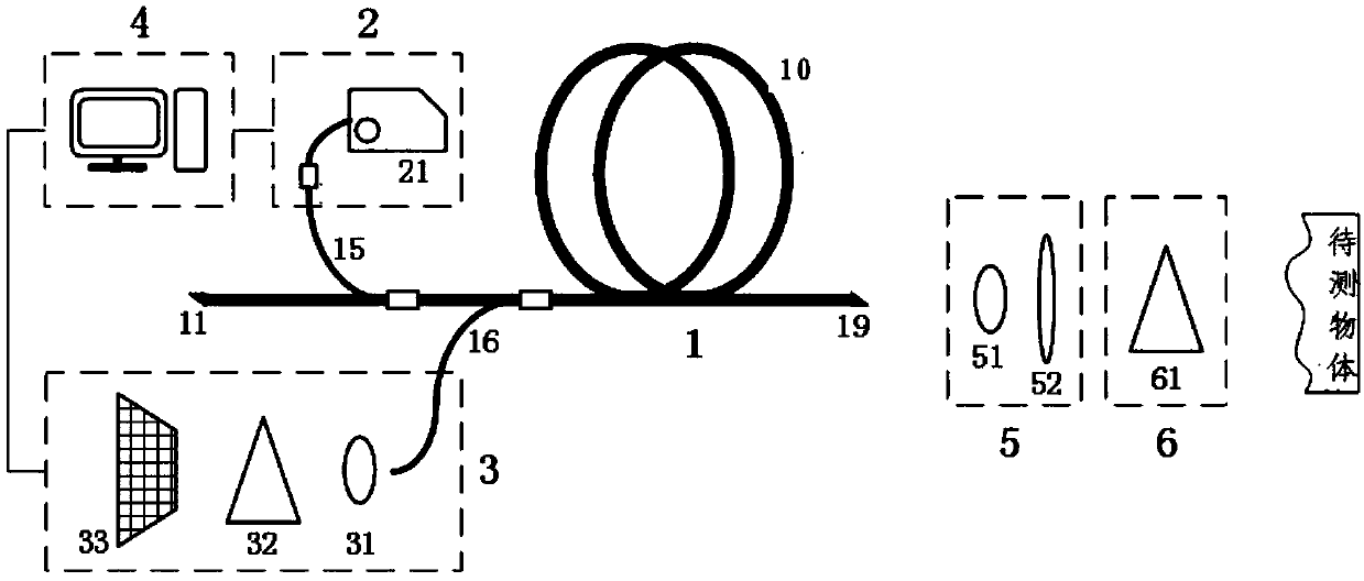
[0024] The specific implementation manners of the present invention will be further described in detail below in conjunction with the accompanying drawings and embodiments. The following examples are used to illustrate the present invention, but are not intended to limit the scope of the present invention.

[0025] Fiber laser is a commonly used laser. By using rare earth-doped glass fiber as the laser gain medium, fiber laser can be developed on the basis of fiber amplifier: under the action of pump light, it is easy to form high power density in the fiber. The laser energy level "particle number inversion" of the laser working material is caused. When the positive feedback loop is properly added, the laser oscillation output can be formed.

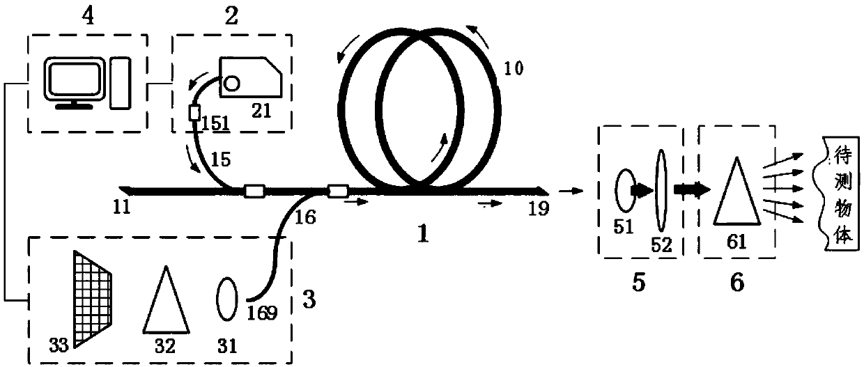
[0026] The cladding pumping technology commonly used in fiber lasers is to inject the pump light required by the fiber laser into the second transmission channel of the fiber, and the pump light crosses the interface between the first tr...


PUM


Abstract

The present invention provides a laser ranging system and method. The system includes a laser emitting module, an emitting and receiving common-optical path module, a laser receiving module, and a calculation module; the emitting and receiving common-optical path module includes a first transmission channel and a second transmission channel; the emitting and receiving common-optical path module isused for obtaining a wide-spectrum light source according to initial laser signals emitted by the laser emitting module, irradiating an object to be measured with the wide-spectrum light source through the first transmission channel, and receiving reflected laser signals through the second transmission channel, wherein the reflected laser signals are reflected back from the object to be measuredafter the broad-spectrum light source irradiates the object to be measured; and the calculation module is used for calculating a distance between the object to be measured and the laser ranging system. According to the laser ranging system and method of the invention, by means of the thinness of an optical fiber and the two laser transmission channels in the same optical fiber, emitting and receiving common-optical path distance measurement is realized; and since the application of a plurality of optical fibers is not required, the size of the probe of the laser ranging system can be greatly decreased, and the probe is more flexible and has higher concealment performance.

Description

technical field [0001] The present invention relates to the field of laser ranging, and more specifically, to a laser ranging system and method. Background technique [0002] At present, laser ranging needs to measure the time difference between the emitted laser signal and the signal returned by the received object, and calculate the distance between the object to be measured and the laser rangefinder through the time difference. In the current laser ranging system, at least one laser emitting probe and one laser receiving probe are included. The laser emitting probe and the laser receiving probe are collectively referred to as probes. laser signal. In order to make the detected signal strong enough, the receiving probe usually needs to occupy a large volume. For example, some laser rangefinders that need to be calibrated have separate transmitters and receivers. In such a system, the optical path space layout is redundant; at the same time, in order to realize the contro...

Claims


Application Information

Patent Timeline
Patent Type & Authority Applications(China)
IPC IPC(8): G01S17/08G01S7/481
CPCG01S7/4811G01S17/08
Inventor 肖起榕闫平巩马理田佳丁李丹
Owner 江西华颂激光科技有限公司
Why Eureka
Try Eureka