Target material assembly machining method

A processing method and component technology, which is applied in metal processing equipment, manufacturing tools, grinding machines, etc., can solve the problems such as the performance and yield of target components need to be improved, so as to improve the cumulative discharge problem, reduce surface lines and edges, and improve uniformity sexual effect

Inactive Publication Date: 2018-04-03
合肥江丰电子材料有限公司
View PDF5 Cites 12 Cited by
  • Summary
  • Abstract
  • Description
  • Claims
  • Application Information

AI Technical Summary

Problems solved by technology

However, the performance and yield of the pr

Method used


Image

  • Target material assembly machining method
  • Target material assembly machining method
  • Target material assembly machining method

Examples


Embodiment Construction

[0027] It can be seen from the background technology that the performance and yield of target components need to be improved. The reason is analyzed in combination with a processing method of target components:

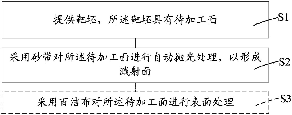
[0028] During the processing of the target assembly, in order to form the sputtering surface of the target blank, polishing is usually achieved by friction between the sandpaper and the surface of the target blank to be processed, thereby reducing the roughness of the sputtering surface of the formed target blank; but the polishing The processing requires manual polishing by manual and machine. Because the uniformity of manual polishing is poor, after polishing, the color difference of the sputtered surface is more obvious, the roughness of the sputtered surface is higher and the roughness uniformity is poor, so As a result, the cumulative number of discharges of the target assembly is relatively high during initial pre-sputtering, so the sputtering performance and yi...


PUM


Abstract

The invention provides a target material assembly machining method. The target material assembly processing method comprises the steps that a target blank with a to-be-machined face is provided; and the to-be-machined face is subjected to automatic polishing treatment through an abrasive belt so as to form a sputtering face. The to-be-machined face is subjected to automatic polishing treatment through the abrasive belt so as to form the sputtering face; on the one hand, compared with abrasive paper, the size of the abrasive belt is larger, therefore, the contact area of the abrasive belt and the to-be-machined face is larger, in order to finish polishing treatment of the whole to-be-machined face, the moving times of the abrasive belt in the direction parallel to the to-be-machined face isdecreased correspondingly, accordingly, surface patterns and edges of the sputtering face are reduced, and the roughness of the sputtering face is reduced; and on the other hand, compared with a manual polishing treatment scheme, according to the automatic polishing method, intensity uniformity during polishing treatment can be improved, accordingly, the roughness uniformity and surface pattern uniformity of the sputtering face are improved, and the cumulative discharge problem of a target material assembly in the initial sputtering stage can be improved.

Description

technical field [0001] The invention relates to the field of semiconductor manufacturing, in particular to a processing method of a target component. Background technique [0002] Liquid crystal display (LCD) has gradually replaced the traditional cathode ray tube (CRT) display with its advantages of no radiation, power saving, and small space, and has been widely used in various fields of production and life, such as computer monitors, notebook computers, Tablet PCs, mobile phones, TVs, monitoring equipment, industrial control instruments, etc. And according to statistics, liquid crystal displays are still growing by more than 10% per year to meet market demand. [0003] The metal target is one of the most important raw materials in the manufacture of liquid crystal displays. The physical vapor deposition process is generally used in the manufacture of liquid crystal displays. During the physical vapor deposition process, the argon ions formed by ionization are accelerated...

Claims


Application Information

Patent Timeline
IPC IPC(8): B24B21/14
CPCB24B21/14
Inventor 姚力军潘杰相原俊夫王学泽李小萍
Owner 合肥江丰电子材料有限公司
Why Eureka
Try Eureka