Heat exchanger structure

A technology of heat exchangers and spiral tubes, which is applied in the field of heat exchanger structure of gas fully premixed condensing wall-hung boilers, can solve the problem that the thermal efficiency of gas fully premixed condensing wall-hung boilers cannot meet the requirements and the localization of heat exchangers Difficulty in production, difficulty in manufacturing heat exchanger products, etc., to achieve the effect of simple structure, easy production and manufacturing, and high yield

Inactive Publication Date: 2018-04-03
SHANGHAI SHUANGKAI GAS APPLIANCE
View PDF0 Cites 14 Cited by
  • Summary
  • Abstract
  • Description
  • Claims
  • Application Information

AI Technical Summary

Problems solved by technology

[0004] In view of the above technical problems, the present invention provides a heat exchanger structure, which solves the difficulty in manufacturing heat exchanger products and the unstable product quality, which leads to the fact

Method used


Image

  • Heat exchanger structure
  • Heat exchanger structure
  • Heat exchanger structure

Examples


Embodiment 1

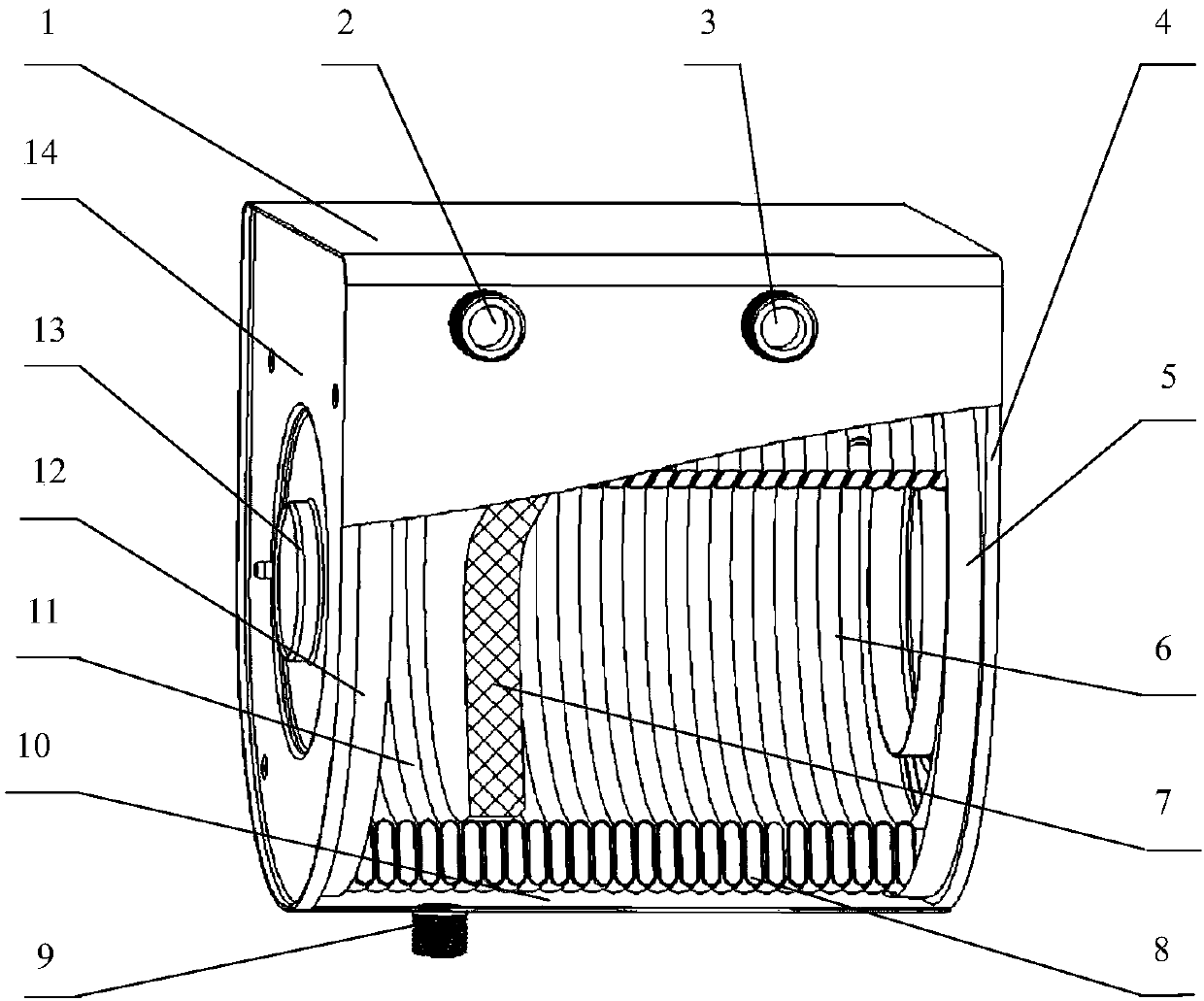
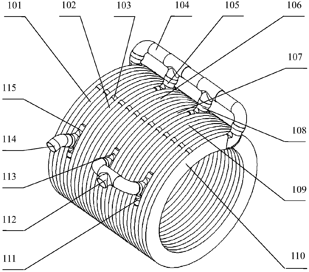
[0026] like figure 1 , 2 As shown, a heat exchanger structure is composed of a shell 1 and an annular coil group 8. The shell 1 has a water inlet 2, a water outlet 3, a condensed water outlet 9 at the bottom, and a rear end cover on the upper side of the shell 1. 14 and the front end cover 4, the rear end cover 14 has an exhaust port 13 and a rear positioning ring 12, the front end cover 4 has a front positioning ring 5, and the annular coil group 8 is fixed inside the housing 1 Between the rear positioning ring 12 and the front positioning ring 5, a spacer cavity 10 is formed between the annular coil group 8 and the housing 1, and a port of the diversion port 114 is connected to the inlet The water outlet 2 is welded together, a port of the confluence port 112 is welded together with the water outlet 3, a heat shield 7 is fixed in the inner cavity of the annular coil group 8, and the inner cavity is divided into a condensation chamber 11 and a In the combustion chamber 6, t...

Embodiment 2

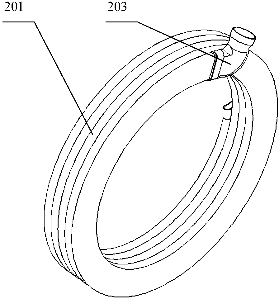
[0031] refer to Figure 5 , provides a schematic diagram of another specific embodiment of the annular coil group in a heat exchanger structure of the present invention, the annular coil group 8 has a long helical tube 301, and the long helical tube 301 is opened Several holes, welding pipe I302, pipe II303, pipe III304, pipe IV305, pipe V306 are welded on the holes, and the connecting pipe 104 is used to connect the first and last ports of the long spiral pipe 301 with the pipe I302, The welded pipe II303 is welded together, the welded pipe III304 and the welded pipe IV305 are welded together by the confluence port 112, the diversion port 114 is welded on the welded pipe V306, and several gap pieces 103 are used for welding On the tube wall of the long helical tube 301, the helical gap is kept the same.

[0032] refer to Image 6 , shows a schematic diagram of a long spiral tube 301 in a heat exchanger structure of this embodiment, and the long spiral tube 301 is welded wit...


PUM

PropertyMeasurementUnit
Thicknessaaaaaaaaaa
Thicknessaaaaaaaaaa

Abstract

The invention provides a heat exchanger structure and particularly provides a heat exchanger structure for a fuel gas full pre-mixing condensation type wall-hung stove. A heat exchanger is the main component of the fuel gas full pre-mixing condensation type wall-hung stove and installed in the fuel gas full pre-mixing condensation type wall-hung stove. The heat exchanger is used for heating heating water. The heat exchanger is composed of a shell and an annular coiler group. The side face of the shell is provided with a water inlet and a water outlet, and a condensed water outlet is formed inthe bottom of the shell. An exhaust opening is formed in the back end cover. The annular coiler group is arranged in the shell and is provided with a plurality of spiral pipes, and the spiral pipes are coaxially connected in series to form a spiral entirety. Water flow in the spiral pipes are distributed through a communicating pipe, a confluence opening and a diversion opening. The gaps of the spiral pipes are kept through spacer sheets. Heat is fully absorbed, and the heat exchange efficiency can be guaranteed. The heat exchanger structure solves the problems of the prior art, and the heat exchanger structure is simple, convenient to produce and manufacture and capable of being manufactured by the adoption of existing domestic production equipment.

Description

technical field [0001] The invention relates to a heat exchanger structure, in particular to a heat exchanger structure for a gas full premixed condensing wall-hung boiler. Background technique [0002] The heat exchanger is the main component of the gas fully premixed condensing wall-hung boiler, which is installed inside the gas fully premixed condensing wall-hung boiler for heating water for heating. The gas combustion products are mainly high-temperature carbon dioxide gas and water vapor. The function of the heat exchanger is to absorb the sensible heat and latent heat of high-temperature carbon dioxide gas and water vapor, and transfer the absorbed heat to the heating water flowing through the heat exchanger. The fully premixed condensing wall-hung boiler is one of the most energy-efficient products in this field. [0003] Among the existing gas-fired fully premixed condensing wall-hung boiler products, the heat exchanger with high heat exchange efficiency and relativ...

Claims


Application Information

Patent Timeline
IPC IPC(8): F24H8/00F24H9/00F28D7/02
CPCF24H8/00F24H8/006F24H9/0005F28D7/024Y02B30/00
Inventor 周宇杰张德超丁培虎
Owner SHANGHAI SHUANGKAI GAS APPLIANCE
Why Eureka
Try Eureka