
Structure of constraining faced wall for building

A technology for combined walls and buildings, applied in building components, building structures, buildings, etc., can solve the problems of large environmental pollution, difficult construction, high resource and energy consumption, and achieve high structural mechanical performance and seismic performance. The effect of low labor intensity and low resource and energy consumption

Pending Publication Date: 2018-04-06
赵建敏 +2
View PDF0 Cites 0 Cited by
  • Summary
  • Abstract
  • Description
  • Claims
  • Application Information

AI Technical Summary

Problems solved by technology

[0003] 1) The structure of reinforced concrete shear wall has a large self-weight, general seismic performance, and slow construction speed. Sometimes the large cross-sectional size of the components has a certain impact on the building space and quality
[0004] 2) The cast-in-place reinforced concrete shear wall belongs to the traditional production method, which consumes high resources and energy, causes great environmental pollution, is labor-intensive, and has low production efficiency
[0005] 3) The prefabricated reinforced concrete shear wall is an industrial production method, but the cost is high, the connection structure is relatively complicated, and the components are heavy, which makes transportation, hoisting and installation inconvenient
[0006] 4) The steel plate shear wall uses a large amount of steel, the cost is high, the anti-corrosion and fire resistance performance is average, the comfort is poor, and the adaptability to the filled wall is general, so its application is greatly restricted
[0007] 5) The square steel pipes in the square steel bundle shear wall have weak constraints on the concrete, the amount of steel used is too large, and the cost is high
[0008] 6) The steel plates in the steel plate composite shear wall structure have weak constraints on the concrete, a large amount of steel is used, the cost is high, the structure is complex, the construction is difficult, and the construction period is long

Method used


Image

  • Structure of constraining faced wall for building
  • Structure of constraining faced wall for building
  • Structure of constraining faced wall for building

Examples


Embodiment Construction

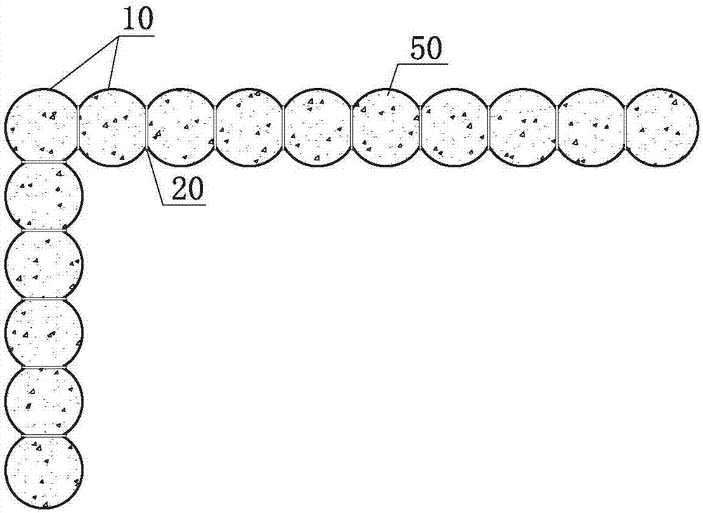
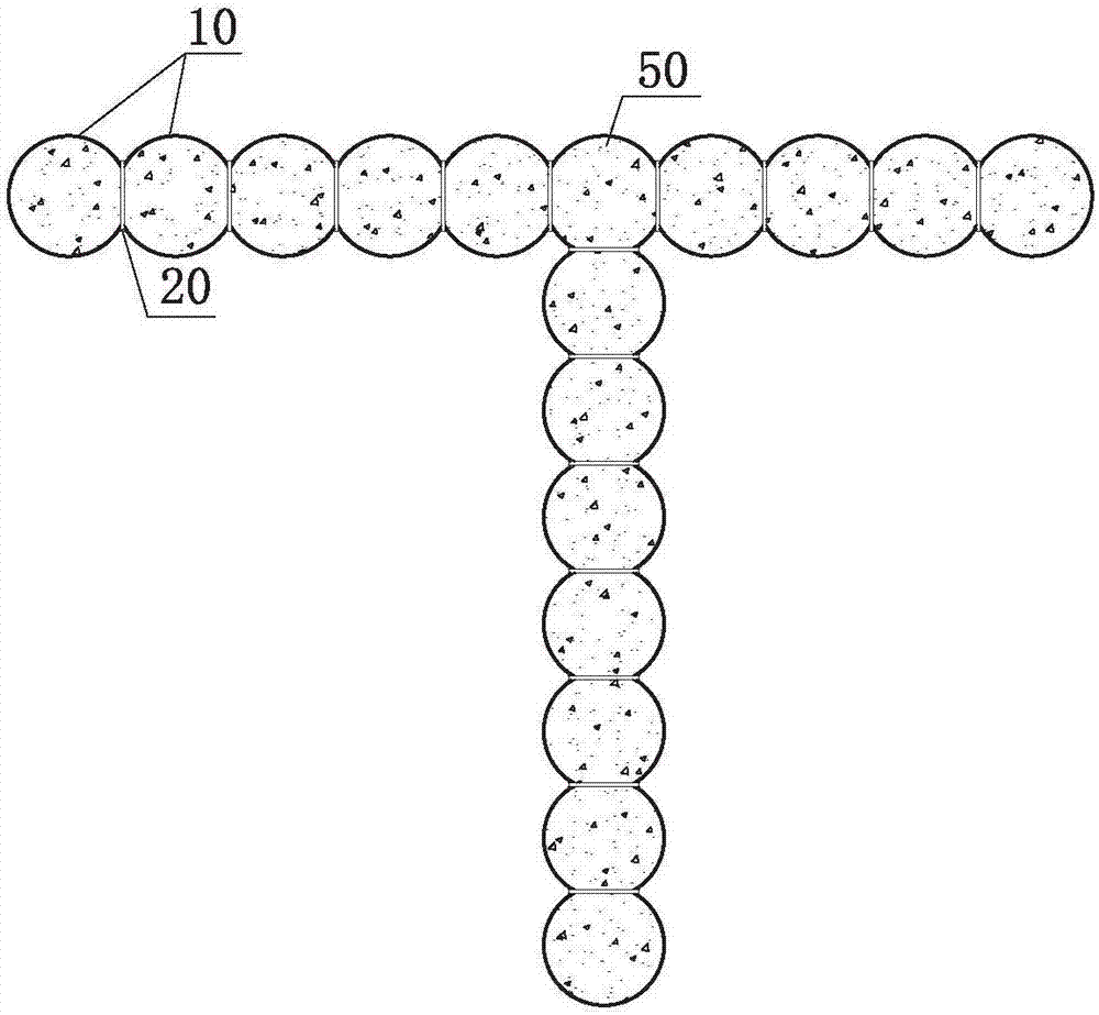
[0019] Such as Figure 1 to Figure 20 As shown, the constrained composite wall structure for construction of the present invention comprises several column units connected to each other to form a cross-section of a predetermined shape, and the aspect ratio of the cross-section is greater than 4; the column units at least include arc-shaped plates 10, and at least one column unit is filled with Filler 50, under normal circumstances, all column units should be filled with filler, but in special cases, a certain column unit or partial structure may not be filled with filler; the column unit is the first column unit, or the second and third columns A combination of units, or a combination of fourth and fifth column units, or a combination of first, second and sixth column units, or a combination of first, fourth and seventh column units, or a combination of second, third and A combination of the eighth column unit, or a combination of the first, second, sixth and eighth column uni...


PUM


Abstract

The invention provides a structure of constraining a faced wall for a building. The structure of constraining the faced wall for the building includes a plurality of column units, and cross section length-width ratio of each of the column units is more than 4. The column units include arc-shaped plates at least. The arc-shaped plates are flexibly connected with slab connecting pieces, circular tubes, polygon tubes and other arc-shaped plates in a fit mode to form the column elements. All the column units or some of the column units are filled with filler. The structure of constraining the faced wall for the building is simple and useful, the material utilization amount is low, the constraining of the quasi-circular structure to the filler is high, the structural bearing and the anti-seismic functions are good, the consumption of resource and energy is low, and the template is not required; and the weight of all components is light, transportation, lifting and installation are convenient and fast, the operation is convenient and fast, the speed of the operation is high, the labor intensity of workers is low, the construction efficiency is high, and the construction cost is low.

Description

technical field [0001] The invention relates to a constrained composite wall structure used in construction engineering, which belongs to the field of construction structure walls. Background technique [0002] At present, in domestic construction projects, reinforced concrete shear walls are widely used, mainly in shear wall structures, frame-shear wall structures, frame-core tube structures, tube-in-tube structures, etc. In addition, cast-in-place Reinforced concrete shear walls, prefabricated reinforced concrete shear walls, steel plate shear walls, square steel beam shear walls, steel plate composite shear walls, etc. also have certain applications. However, from the point of view of actual use, the wall structures of the above-mentioned forms all have certain defects: [0003] 1) Reinforced concrete shear walls are self-heavy, generally anti-seismic performance, and the construction speed is slow. Sometimes, the large cross-sectional size of the components has a certai...

Claims


Application Information

Patent Timeline
IPC IPC(8): E04B2/56E04B1/98E04H9/02
CPCE04B2/56E04H9/02
Inventor 赵建敏刘明辉王东方
Owner 赵建敏
Learn More