Three-cone drill bit for particle impact drilling

A particle impact, tri-cone technology, applied in drill bits, drilling equipment, earth-moving drilling and other directions, can solve the problems of long drilling cycle, high development cost, lowering the development benefit of deep oil and gas resources, etc., to avoid direct impact on the cone. It has the effect of low cost of processing and production of teeth and avoiding operation risks.

Pending Publication Date: 2018-04-13
CHINA NAT PETROLEUM CORP CHUANQING DRILLING ENG CO LTD +1
View PDF0 Cites 3 Cited by
  • Summary
  • Abstract
  • Description
  • Claims
  • Application Information

AI Technical Summary

Problems solved by technology

[0002] With the gradual depletion of shallow oil and gas resources in my country, the development of deep oil and gas resources is accelerating. During the drilling of deep and ultra-deep wells, hard formations and strong abrasive formations have become an important factor restricting the ROP. Take the Xujiahe and Zhenzhuchong Formation as an example, the average ROP of the roller cone bit is only 0.7-1.34 m/h, and the footage of the hard formation and strong abrasive formation accounts for 4%-10% of the total well, but the drilling time However, it accounts for 25-30% of the drilling cycle of the whole well. Low drilling speed and long drilling time bring about long drilling cycle and high development cost, which restricts the overall development benefits of deep oil and gas resources; at the same time, the roller cone bit In hard formations with drilling speed and strong abrasive formations, the phenomenon of tooth wea

Method used


Image

  • Three-cone drill bit for particle impact drilling
  • Three-cone drill bit for particle impact drilling
  • Three-cone drill bit for particle impact drilling

Examples


Example Embodiment

[0022] Example 1

[0023] As a preferred embodiment of the present invention, refer to the appendix Figure 1-4 , This embodiment discloses:

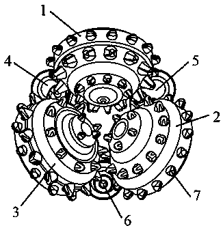
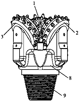
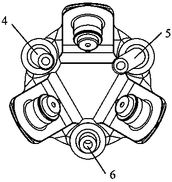
[0024] A three-cone drill bit for particle impact drilling, comprising a bit body 8, a joint 9, a first claw 10, a second claw 11, a third claw 12, a first cone 1, a second cone 2, and three No. 1 cone 3, No. 1 particle jet modulation nozzle 4, No. 2 particle jet modulation nozzle 5, and No. 3 particle jet modulation nozzle 6, the No. 1 cone 1, No. 2 cone 2, and No. 3 cone 3 pass through bearings The mechanism is respectively connected and assembled with No. 1 tooth claw 10, No. 2 tooth claw 11 and No. 3 tooth claw 12, No. 1 particle jet modulation nozzle 4 is located between No. 1 cone 1 and No. 3 cone 3, No. 2 particle jet modulation Nozzle 5 is located between No. 1 cone 1 and No. 2 cone 2, No. 3 particle jet modulation nozzle 6 is located between No. 2 cone 2 and No. 3 cone 3; the No. 1 particle jet modulation nozzle 4, 2 No. 3 particl...

Example Embodiment

[0025] Example 2

[0026] As another preferred embodiment of the present invention, refer to the appendix of the specification Figure 1-5 , This embodiment discloses:

[0027] A three-cone drill bit for particle impact drilling, comprising a bit body 8, a joint 9, a first claw 10, a second claw 11, a third claw 12, a first cone 1, a second cone 2, and three No. 1 cone 3, No. 1 particle jet modulation nozzle 4, No. 2 particle jet modulation nozzle 5, and No. 3 particle jet modulation nozzle 6, the No. 1 cone 1, No. 2 cone 2, and No. 3 cone 3 pass through bearings The mechanism is respectively connected and assembled with No. 1 tooth claw 10, No. 2 tooth claw 11 and No. 3 tooth claw 12, No. 1 particle jet modulation nozzle 4 is located between No. 1 cone 1 and No. 3 cone 3, No. 2 particle jet modulation Nozzle 5 is located between No. 1 cone 1 and No. 2 cone 2, No. 3 particle jet modulation nozzle 6 is located between No. 2 cone 2 and No. 3 cone 3; the No. 1 particle jet modulatio...

Example Embodiment

[0029] Example 3

[0030] As another preferred embodiment of the present invention, refer to the appendix of the specification Figure 1-5 , This embodiment discloses:

[0031] A three-cone drill bit for particle impact drilling, comprising a bit body 8, a joint 9, a first claw 10, a second claw 11, a third claw 12, a first cone 1, a second cone 2, and three No. 1 cone 3, No. 1 particle jet modulation nozzle 4, No. 2 particle jet modulation nozzle 5, and No. 3 particle jet modulation nozzle 6, the No. 1 cone 1, No. 2 cone 2, and No. 3 cone 3 pass through bearings The mechanism is respectively connected and assembled with No. 1 tooth claw 10, No. 2 tooth claw 11 and No. 3 tooth claw 12, No. 1 particle jet modulation nozzle 4 is located between No. 1 cone 1 and No. 3 cone 3, No. 2 particle jet modulation Nozzle 5 is located between No. 1 cone 1 and No. 2 cone 2, No. 3 particle jet modulation nozzle 6 is located between No. 2 cone 2 and No. 3 cone 3; the No. 1 particle jet modulatio...


PUM

PropertyMeasurementUnit
Inlet diameteraaaaaaaaaa

Abstract

The invention relates to a tri-cone drill bit for particle impact drilling, which is composed of claws, cones, teeth, a particle jet modulation nozzle, a joint and a bit body, wherein the particle jet modulation nozzle is made of hard alloy material, and is connected with the drill bit by brazing. The drill bit body is connected; the outlet position and inclination angle of each nozzle are different, and the arrangement positions of the teeth on the three cones are also different. It passes through the gap between the cone and the cone to avoid the direct impact of the particle jet on the cone and the teeth. The present invention adopts the working method of particle jet impact rock-breaking drilling, supplemented by mechanical rock-breaking drilling of the cone and teeth. The drilling efficiency of the highly abrasive formation is much better than that of the existing roller cone bit, and in extreme cases, when the ground particle injection system fails, the present invention can also be used as an ordinary roller cone bit for rock-breaking drilling. Effectively avoid operational risks.

Description

technical field [0001] The invention relates to the technical field of petroleum engineering drilling, in particular to a tri-cone drill bit for particle impact drilling. Background technique [0002] With the gradual depletion of shallow oil and gas resources in my country, the development of deep oil and gas resources is accelerating. During the drilling of deep and ultra-deep wells, hard formations and strong abrasive formations have become an important factor restricting the ROP. Take the Xujiahe and Zhenzhuchong Formation as an example, the average ROP of the roller cone bit is only 0.7-1.34 m / h, and the footage of the hard formation and strong abrasive formation accounts for 4%-10% of the total well, but the drilling time However, it accounts for 25-30% of the drilling cycle of the whole well. Low drilling speed and long drilling time bring about long drilling cycle and high development cost, which restricts the overall development benefits of deep oil and gas resources;...

Claims


Application Information

Patent Timeline
IPC IPC(8): E21B10/08E21B10/16E21B10/18E21B7/16
CPCE21B7/16E21B10/08E21B10/16E21B10/18
Inventor 韩烈祥张治发张帆乔李华万夫磊张果尹晓煜
Owner CHINA NAT PETROLEUM CORP CHUANQING DRILLING ENG CO LTD
Why Eureka
Try Eureka