An engine with a water injection system

A technology of water spray system and engine, which is applied in the direction of engine components, engine cooling, machine/engine, etc. It can solve the problems of spark plug cooling difficulty, pre-combustion chamber cooling difficulty, and low feasibility, so as to ensure durability and low The failure rate and the effect of reducing the frequency of water addition

Active Publication Date: 2021-07-02
ZHEJIANG GEELY HOLDING (GROUP) CO LTD +1
View PDF7 Cites 0 Cited by
  • Summary
  • Abstract
  • Description
  • Claims
  • Application Information

AI Technical Summary

Problems solved by technology

However, the temperature of the pre-chamber itself is too high, it is difficult to cool the pre-chamber, and it is difficult to cool the spark plug.
The current solution is to redesign the cylinder head water jacket, but the workload is heavy and the feasibility is not high; or add water channels outside the pre-combustion chamber, but the effect is not good

Method used


Image

  • An engine with a water injection system
  • An engine with a water injection system
  • An engine with a water injection system

Examples


Embodiment 1

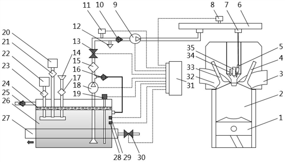
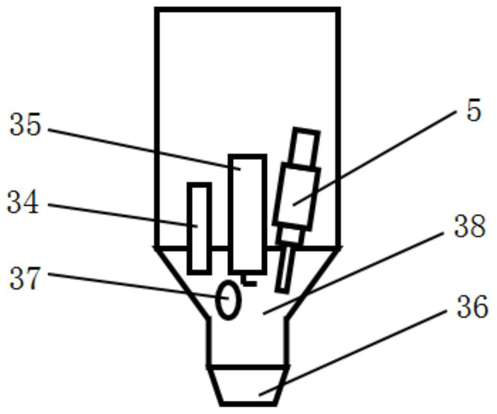
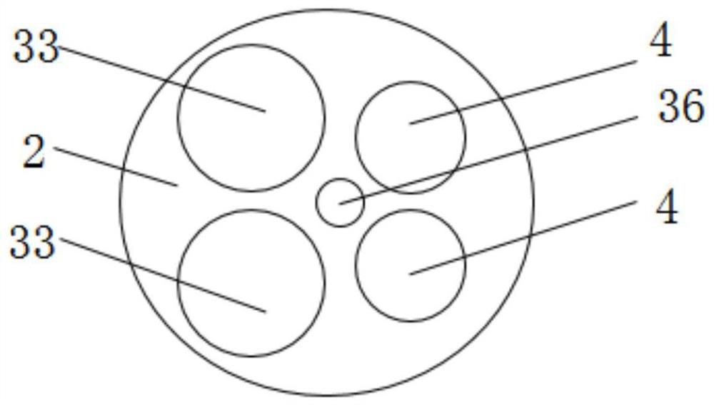
[0036] see Figure 1-3 . As shown in the figure, the present invention discloses an engine with a water injection system, including a main combustion chamber 2, a pre-combustion chamber 38 and a water injection system, and the main combustion chamber 2 is connected with the pre-combustion chamber 38 through a nozzle 36 In general, the pre-combustion chamber 38 is provided with a first intake port 37 , an injector 34 and a spark plug 35 , and the first intake port 37 is used for introducing a mixture gas with a higher concentration.

[0037]The water spray system includes a water supply device, a spray device and an electronic control unit 31, and the water supply device communicates with the spray device through a water pipe; the water supply device includes a water storage tank 26, a second water pump 18 and an accumulator 11. The second water pump 18 and the accumulator 11 are sequentially arranged along the water pipe, the water inlet and the water outlet of the second wat...

Embodiment 2

[0044] The invention discloses an engine with a water injection system, including a main combustion chamber 2, a pre-combustion chamber 38 and a water spray system, the main combustion chamber 2 communicates with the pre-combustion chamber 38 through a nozzle 36, the pre-combustion chamber The combustion chamber 38 is provided with a first intake port 37 , a fuel injector 34 and a spark plug 35 , and the first intake port 37 is used for introducing a mixed gas with a higher concentration.

[0045] The water spray system includes a water supply device, a spray device and an electronic control unit 31, and the water supply device communicates with the spray device through a water pipe; the water supply device includes a water storage tank 26, a second water pump 18 and an accumulator 11. The second water pump 18 and the accumulator 11 are sequentially arranged along the water pipe, the water inlet and the water outlet of the second water pump 18 communicate with the water pipe re...


PUM


Abstract

The invention discloses an engine with a water injection system, which includes a main combustion chamber, a pre-combustion chamber and a water injection system. The water injection system includes a water supply device, an injection device and an electronic control unit. The water supply device and the injection device are connected through a water pipe The water supply device includes a water storage tank, a second water pump and an accumulator, and the second water pump is arranged between the water storage tank and the accumulator; the injection device includes a first water pump, a water pressure sensor and a water sprayer, and the first water pump is close to the energy storage The sprinkler is set, and the sprinkler is set in the pre-chamber. In the present invention, a water spray system is provided in the engine, and the nozzle is arranged in the pre-combustion chamber. Compared with redesigning the cylinder head water jacket of the combustion chamber, the water spray system can reduce the internal temperature of the pre-combustion chamber more quickly and effectively; The water source in the water tank comes from the water injection port, the condensed water of the EGR system and the condensed water of the air conditioner, which reduces the frequency of daily driving.

Description

technical field [0001] The invention relates to the field of automobile engines, in particular to an engine with a water spray system. Background technique [0002] Future gasoline engines need to provide users with high torque, high power and low cost products while meeting increasingly stringent fuel consumption and emission regulations. Although high compression ratio, small supercharger combined with direct injection technology can maximize the thermal efficiency of the engine, the efficiency and performance improvement of the engine is limited by knocking. Usually, knocking can be suppressed by using cooling EGR technology, variable compression ratio, and miller cycle. , lean combustion, water injection technology, pre-combustion chamber technology, etc. The pre-combustion chamber technology is to divide the combustion chamber into a main combustion chamber and a pre-(secondary) combustion chamber. The two chambers are connected by a channel, and the mixed gas in the pr...

Claims


Application Information

Patent Timeline
Patent Type & Authority Patents(China)
IPC IPC(8): F01P3/12F01P3/02F01P7/16F01P11/02F01P11/16F01P11/18
CPCF01P3/02F01P3/12F01P7/16F01P11/0276F01P11/16F01P11/18
Inventor 苏杭余敬周张华杨林李连豹韦虹李双清李军王瑞平
Owner ZHEJIANG GEELY HOLDING (GROUP) CO LTD
Why Eureka
Try Eureka