Chemical etching measurement method for optical element sub surface damages, auxiliary experiment device and test method

A technology of subsurface damage and chemical etching, which is applied in the direction of measuring devices, test sample preparation, instruments, etc., can solve the problems of difficulty in ensuring accuracy, impracticality, high equipment requirements, etc., to overcome the danger of manual operation, measure The effect of low equipment requirements and low equipment requirements

Active Publication Date: 2018-04-13
XI AN JIAOTONG UNIV
View PDF10 Cites 12 Cited by
  • Summary
  • Abstract
  • Description
  • Claims
  • Application Information

AI Technical Summary

Problems solved by technology

In this method, the establishment of related models is very important, and the measurement accuracy has a great relationship with the establishment of the model, and it is not easy to guarantee the accuracy
Patent "Measurement method for the thickness of the subsurface damage layer of hard and brittle optical materials" (Wang Hairong, Chen Can, Ren Junqiang, Sun Guoliang, Yuan Guoying, Jiang Zhuangde. Measurement method for the thickness of the subsurface damage layer of hard and brittle optical materials: China, 200910024280[P ].2009.10.13) Need to use magnetorheological polishing technology, magnetorheological polishing takes a long time and requires relatively high equipment, which is not practical

Method used


Image

  • Chemical etching measurement method for optical element sub surface damages, auxiliary experiment device and test method
  • Chemical etching measurement method for optical element sub surface damages, auxiliary experiment device and test method
  • Chemical etching measurement method for optical element sub surface damages, auxiliary experiment device and test method

Examples


Embodiment 1

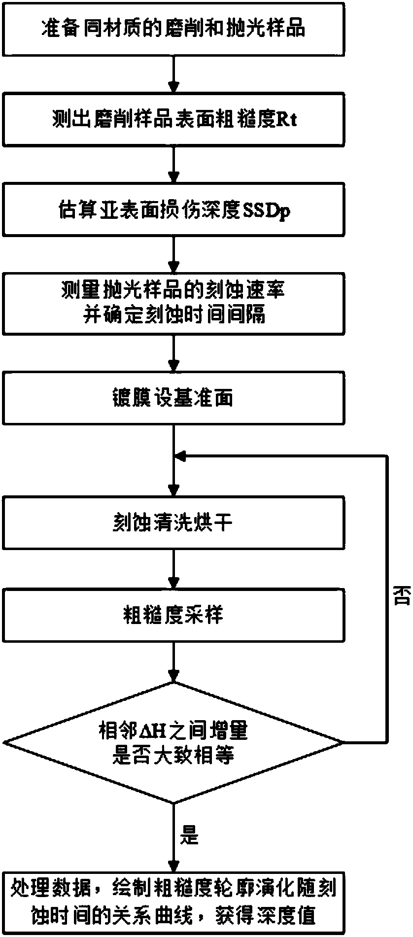
[0074] Examples of subsurface damage depth measurements (see figure 1 ):

[0075] (1) Prepare ground and polished samples of the same material. The sample is cylindrical ground and polished K9 glass with a diameter of 30 mm and a thickness of 3 mm, and self-prepared etching solutions: HF and HNO 3 A mixed solution with HF concentration of 40%, HNO 3 The concentration is 65%, the volume ratio is HF:HNO 3 =4:1;

[0076] (2) Use a step meter to randomly measure the roughness of 8 points of the sample grinding sample, and obtain the average value R t =9.6um;

[0077] (3) The theoretical model of the relationship between the grinding subsurface damage depth and surface roughness estimates the subsurface damage depth SSD p :

[0078]

[0079] a k =0.027+0.090(m-1 / 3)=0.027, m=1 / 3

[0080]

[0081] ψ=46°, E=72GPa, H=6GPa, K c =0.75

[0082] SSD p =48.109um;

[0083](4) To measure the etching rate v of the sample, take 9 pieces of polished glass of the same shape as t...

Embodiment 2

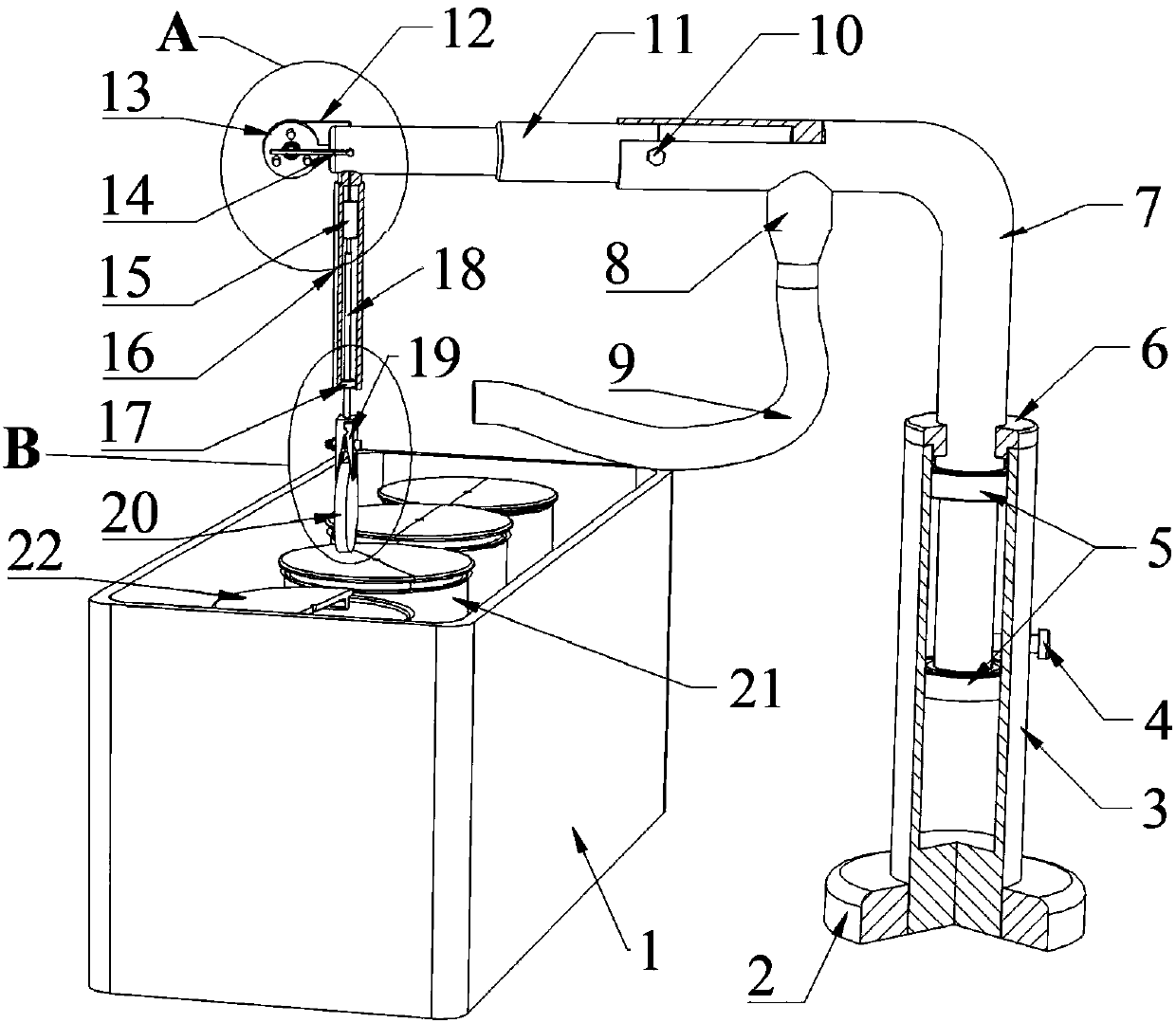
[0090] Examples of chemical etching auxiliary devices:

[0091] The process of using the chemical etching auxiliary device is: HF acid etching for 3 minutes, acetone solution cleaning for 3 minutes, alcohol solution cleaning for 3 minutes, ultra-clean water cleaning for 3 minutes, and drying. The ultrasonic oscillator is turned on during the cleaning process, and the blower and motor are turned on during the drying process, so that the blower is aimed at the rotating sample to blow air.

[0092] like image 3 and Figure 4 As shown, the chemical etching auxiliary device mentioned in the above method includes: ultrasonic oscillator 1, support 2, first support rod 3, first fixing bolt 4, first bearing 5, end cover 6, second support Rod 7, blower 8, universally adjustable jet pipe 9, second fixing bolt 10, beam 11, winding wire 12, reel 13, limit rod 14, motor 15, vertical rod 16, second bearing 17, connecting shaft 18. Sample holder 19, sample 20, beaker 21, beaker cover 22, ...


PUM


Abstract

The invention relates to a chemical etching measurement method for optical element sub surface damages, an auxiliary experiment device and a test method. In the chemical etching measurement method, through measuring the roughness of a sample during the etching process, an evolutional relation curve for roughness outlines along with the etching time is drawn, and a sub surface damage depth value isthus obtained. The chemical etching auxiliary device is used to realize etching, cleaning and drying on the optical element, an ultrasonic vibration instrument is added during the cleaning process toassist cleaning, and a hair drier and a motor are added during the drying process to assist drying. The sub surface damage depth can be quickly and accurately measured; a set of etching auxiliary device is designed, the device is simple in operation, high in efficiency and low in danger, sediments generated during the etching process can be effectively reduced, and influences on etching and measurement are greatly reduced.

Description

technical field [0001] The invention relates to a chemical etching measurement method, an auxiliary experimental device and a test method for optical element subsurface damage, and relates to the technical field of grinding subsurface damage depth measurement. technical background [0002] As an efficient and inexpensive processing technology, grinding technology is widely used in the forming process of high-precision optical components. However, due to the hard and brittle nature of optical components, subsurface damage such as microcracks, scratches, and residual stress inevitably occurs during the grinding process of optical components. For optical components, subsurface damage will reduce their strength, stability and laser damage resistance threshold, change their optical properties and affect some important performance indicators. Therefore, it is crucial to assess the depth of subsurface damage due to grinding. [0003] In the patent "Measurement method for the thic...

Claims


Application Information

Patent Timeline
Patent Type & Authority Applications(China)
IPC IPC(8): G01B21/18G01N1/32
CPCG01B21/18G01N1/32
Inventor 王海容陈志肖华攀余娜
Owner XI AN JIAOTONG UNIV
Why Eureka
Try Eureka