
Optical F-P resonant cavity for frequency stabilization of semiconductor laser

A laser and semiconductor technology, applied in semiconductor lasers, optical resonator structures, lasers, etc., can solve the problems of difficult laser frequency pullback, lack of universality, and high process complexity, achieving simple structure and simple assembly. , the effect of reducing the size

Inactive Publication Date: 2018-04-13
NO 49 INST CHINESE ELECTRONICS SCI & TECH GRP
View PDF0 Cites 0 Cited by
  • Summary
  • Abstract
  • Description
  • Claims
  • Application Information

AI Technical Summary

Problems solved by technology

However, under normal circumstances, the process complexity of making a micro air chamber is high, and it is difficult to manufacture, and this kind of air chamber needs to be equipped with a heater and a temperature sensor when it is working.
In order to avoid the influence of heat transfer, other optical components in the frequency stabilization optical path have to keep a certain distance from the gas chamber, so it is difficult to further reduce the volume of the optical path
In addition, if the laser frequency jumps, it is difficult for this frequency stabilization system to pull the laser frequency back to the original center frequency
For lasers with different wavelengths, it is necessary to make gas cells of different atoms / molecules. Such a frequency stabilization scheme is obviously not universal

Method used


Image

  • Optical F-P resonant cavity for frequency stabilization of semiconductor laser
  • Optical F-P resonant cavity for frequency stabilization of semiconductor laser
  • Optical F-P resonant cavity for frequency stabilization of semiconductor laser

Examples


specific Embodiment approach 1

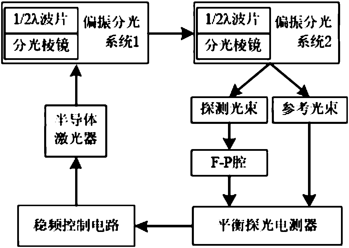
[0021] Specific implementation mode one: combine figure 1 Specifically illustrate this embodiment mode, a kind of optical F-P resonator that is used for semiconductor laser frequency stabilization in this embodiment mode is made of the first silicon dioxide substrate 1, the second silicon dioxide substrate 2, the 3rd silicon dioxide substrate 3, The fourth silicon dioxide substrate 4, the fifth silicon dioxide substrate 5, the sixth silicon dioxide substrate 6, and the seventh silicon dioxide substrate 7;

[0022] The lower surface of the first silicon dioxide substrate 1 is provided with a second silicon dioxide substrate 2, and the first silicon dioxide substrate 1 and the second silicon dioxide substrate 2 are arranged in dislocation, and the second silicon dioxide substrate 2 is located at the lower right of the first silicon dioxide substrate 1;

[0023] The lower surface of the second silicon dioxide substrate 2 is provided with a third silicon dioxide substrate 3, and ...

specific Embodiment approach 2

[0038] Embodiment 2: The difference between this embodiment and Embodiment 1 is that the thickness of the first silicon dioxide substrate 1 is 10 microns to 500 microns. Others are the same as in the first embodiment.

specific Embodiment approach 3

[0039] Embodiment 3: This embodiment differs from Embodiment 1 or Embodiment 2 in that: the thickness of the second silicon dioxide substrate 2 is 10 microns to 500 microns. Others are the same as in the first or second embodiment.


PUM


Abstract

An optical F-P resonant cavity used for frequency stabilization of semiconductor lasers, the invention relates to an optical F-P resonant cavity. The invention aims to solve the problem that in the atomic / molecular spectrum frequency stabilization system used in semiconductor lasers, the atomic / molecular gas chamber is the core frequency reference device. The process of making a micro gas chamber is complex and difficult to manufacture, and this kind of gas chamber needs to be equipped with a heater and a temperature sensor when it is working. It is difficult to further reduce the volume of the optical path. If the laser frequency jumps, this frequency stabilization system It is difficult to pull the laser frequency back to the original center frequency. The optical F-P resonator consists of the first silicon dioxide substrate, the second silicon dioxide substrate, the third silicon dioxide substrate, the fourth silicon dioxide substrate, the fifth silicon dioxide substrate, the sixth and second It consists of a silicon oxide substrate and a seventh silicon dioxide substrate.

Description

technical field [0001] The invention relates to an optical F-P resonant cavity. Background technique [0002] Semiconductor lasers are widely used in optical communication, optical sensing and other fields because of their small size, low power consumption, large wavelength coverage, and easy tuning and modulation. The laser is affected by the surrounding environment and its own factors, such as the material properties inside the laser, cavity length, carrier concentration, gain, energy gap, refractive index, temperature, mechanical vibration and operating current, etc., which will cause the output frequency to be unstable. , and often changes over time. Therefore, it is of great significance to study the frequency stabilization of lasers. If its frequency stability problem can be improved, it will open up broader application prospects for semiconductor lasers. The spectral lines of atoms or molecules show relatively stable properties and are less affected by external fac...

Claims


Application Information

Patent Timeline
Patent Type & Authority Applications(China)
IPC IPC(8): H01S5/10H01S5/0687
CPCH01S5/10H01S5/0687
Inventor 桂永雷王世宁邓从杰孙力凯
Owner NO 49 INST CHINESE ELECTRONICS SCI & TECH GRP
Learn More