A Combined Interferometric Cavity for Wavelength Selective Output of Chemical Lasers

A wavelength selection and laser technology, applied in the field of combined interference cavity, to achieve the effect of avoiding insertion loss and high anti-damage threshold

Active Publication Date: 2019-08-02
DALIAN INST OF CHEM PHYSICS CHINESE ACAD OF SCI
View PDF5 Cites 0 Cited by
  • Summary
  • Abstract
  • Description
  • Claims
  • Application Information

AI Technical Summary

Problems solved by technology

However, there are no reports on the resolution and selection of chemical laser wavelengths using these methods.

Method used


Image

  • A Combined Interferometric Cavity for Wavelength Selective Output of Chemical Lasers
  • A Combined Interferometric Cavity for Wavelength Selective Output of Chemical Lasers
  • A Combined Interferometric Cavity for Wavelength Selective Output of Chemical Lasers

Examples


Embodiment Construction

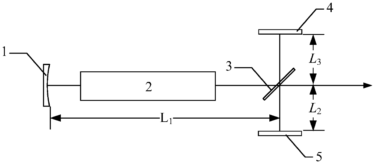
[0020] as attached figure 1 As shown, a combined interference cavity for chemical laser wavelength selective output, the laser resonator includes a concave cut-off mirror 1, a laser gain region 2, a 45-degree beam splitter 3, a first plane cut-off mirror 4, a second Flat cut-off mirror 5. All optical components are fixed on a vibration-isolation platform in a vacuum chamber. The optical axis of the optical cavity passes through the centers of the concave cut-off mirror 1, the laser gain region 2, the reflective surface of the 45-degree beam splitter 3, the first plane cut-off mirror 4, and the second plane cut-off mirror 5 respectively. The first plane cut-off mirror 4, the 45-degree beam splitter 3 and the second plane cut-off mirror 5 jointly constitute the interference sub-cavity of the laser optical cavity; the first plane cut-off mirror 4 is arranged opposite to the second plane cut-off mirror 5, They are respectively located on both sides of the 45-degree beam splitter...


PUM


Abstract

The invention relates to a combined interference chamber for chemical laser device wavelength choice output. A stable chamber structure is adopted in the combined interference chamber which comprisesa recessed surface reflecting mirror, a 45 degree beam splitting sheet and two plane reflecting mirrors. The 45 degree beam splitting sheet and the two plane reflecting mirrors form an interference sub-chamber, and reflecting films having different reflectivity for laser light with different wavelengths are respectively plated on reflecting planes of the recessed surface reflector and the plane reflecting mirrors. Via control over reflectivity parameters of optical elements in a laser resonant cavity, wavelengths of a laser device can be chosen roughly; interference effects are used for closely adjacent wavelengths can be chosen in a careful way via adjustment of parameters such as a length of the interference sub-chamber, a beam splitting ratio of a beam splitting sheet and the like; thelaser device is enabled to output laser light with any single wavelength.

Description

technical field [0001] The invention belongs to the field of chemical lasers, in particular to a combined interference cavity used for wavelength selective output of chemical lasers. Background technique [0002] Mid-infrared lasers work in the atmospheric window band, and have important application value and prospects in the fields of laser spectroscopy, laser remote sensing, environmental monitoring, laser medical treatment, and infrared countermeasures. In recent years, the development of mid-infrared lasers has been highly concerned by domestic and foreign scientific research institutions and has been developed rapidly. [0003] Since Spencer and others introduced pneumatic technology into chemical lasers in 1969, solved the rapid mixing of reactants, and realized the first continuous wave hydrogen fluoride / deuterium fluoride (HF / DF) laser, HF / DF lasers have become the current development The most mature and largest mid-infrared strong laser system. For continuous wave...

Claims


Application Information

Patent Timeline
Patent Type & Authority Patents(China)
IPC IPC(8): H01S3/10H01S3/101
CPCH01S3/10H01S3/101
Inventor 王元虎多丽萍金玉奇唐书凯李国富于海军汪健曹靖康元福
Owner DALIAN INST OF CHEM PHYSICS CHINESE ACAD OF SCI
Why Eureka
Try Eureka