
Machine for directly driving spiral motion motor and use of machine

A technology of helical motion and machinery, which is applied to rotary drilling rigs, grinding machine parts, electromechanical devices, etc., can solve the problems of inconvenient installation, dismantling, handling, and large size of construction machinery, and achieves low cost, simple structure, The effect of small mechanical size

Inactive Publication Date: 2018-04-17
王政玉
View PDF0 Cites 0 Cited by
  • Summary
  • Abstract
  • Description
  • Claims
  • Application Information

AI Technical Summary

Problems solved by technology

In particular, the feed system generally adopts a hydraulic or pneumatic control system. This feed system requires a bulky hydraulic workstation or compressed air station in addition to the actuator and control device, resulting in a relatively large volume of the construction machine. Large size, oil leakage, air leakage, and inconvenient installation, removal, and transportation

Method used


Image

  • Machine for directly driving spiral motion motor and use of machine
  • Machine for directly driving spiral motion motor and use of machine

Examples


Embodiment 1

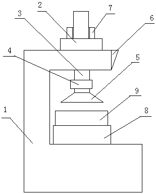
[0033] Example 1: figure 1 It is a schematic diagram of the basic structure of a surface grinder directly driven by a spiral motion motor of the present invention. The surface grinder includes: the frame 1 is equipped with a spiral motion motor 2, the mover 3 of the spiral motion motor 2 is directly used as the main shaft of the grinder, the main shaft 3 is equipped with a fixture 4 and a grinding head 5, and the spiral motion generated by the spiral motion motor 2 replaces the existing one. The rotary motion of the main motor of the grinder and the linear motion of the hydraulic feed mechanism, the electric control unit 6 is connected to the screw motion motor 2, and the electromagnetic clamping device 7 is installed between the mover 3 of the screw motion motor 2 and the frame 1 , the frame 1 is equipped with a liftable workbench 8, and the liftable workbench 8 can be adjusted in height according to the size of the workpiece 9. When the grinding machine is in operation, fir...

Embodiment 2

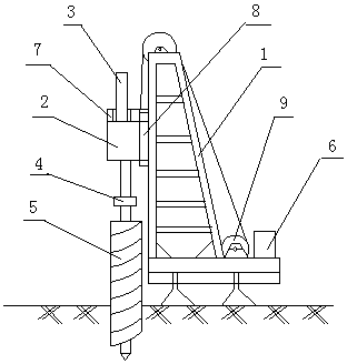
[0034] Example 2: figure 2 It is a schematic diagram of the basic structure of an auger drill directly driven by a helical motion motor of the present invention. The auger drilling machine includes: a helical motion motor 2 is installed on the frame 1, and the mover 3 of the helical motion motor 2 is directly used as the main shaft of the auger drilling machine, and the clamp 4 and the auger bit 5 are installed on the main shaft 3, and the helical motion generated by the helical motion motor 2 replaces the The rotary motion of the main motor of the existing engineering drilling rig and the linear motion of the hydraulic feed mechanism, the electric control unit 6 is connected to the screw motion motor 2, and the electromagnetic clamping device is installed between the mover 3 of the screw motion motor 2 and the frame 1 Device 7, a guide rail 8 is installed between the frame 1 and the screw motor 2, the screw motor 2 can move up and down along the guide rail 8 under the action...


PUM


Abstract

The invention provides a machine directly driven by a spiral motion motor and its application. A spiral motion motor is installed on the frame of the machine. The spiral motion generated by the motion motor replaces the rotary motion of the main motor of the existing machinery and the linear motion of the feed mechanism. The power control unit is connected to the spiral motion motor, and a clamping device is installed between the mover and the frame of the spiral motion motor. Or a hovering device or a braking device; the present invention has the characteristics of simple structure, low cost, convenient control, etc., and can be used for various mechanical processing and engineering construction machines.

Description

technical field [0001] The invention belongs to the electromechanical field, and in particular relates to mechanical processing and engineering construction machinery. Background technique [0002] Existing mechanical processing machine tools, such as drilling machines, milling machines, grinding machines, etc., generally consist of mechanical racks, workbenches, spindles, columns, power units, control units, transmission systems, feed systems, cutting fluid or abrasive supply units, Clamping device, processing tool head and other components. In particular, the feed system generally adopts a hydraulic or pneumatic control system or a manual device. This feed system requires a bulky hydraulic workstation or compressed air station in addition to the actuator and the control device. The overall volume is large, oil leakage, air leakage and other problems. [0003] Existing engineering construction machinery, such as: construction or well drilling, piling and other machinery, ...

Claims


Application Information

Patent Timeline
Patent Type & Authority Applications(China)
IPC IPC(8): H02K16/00B24B47/02B24B47/20E21B3/02E21B15/00
CPCH02K16/00B24B47/02B24B47/20E21B3/02E21B15/00
Inventor 王政玉王超颖岑陈张玉芹
Owner 王政玉
Learn More