Air compressor heat recovery device control system

A heat recovery device and control system technology, which is applied in pump control, mechanical equipment, machine/engine, etc., can solve problems such as difficult to improve equipment production efficiency and utilization rate, inability to recycle, heat can not be used, etc., to achieve heat Effects of recycling, reducing heat waste, and saving energy

Pending Publication Date: 2018-04-20
NINGBO XUNHUI ELECTRIC APPLIANCE
View PDF6 Cites 1 Cited by
  • Summary
  • Abstract
  • Description
  • Claims
  • Application Information

AI Technical Summary

Problems solved by technology

Now all the machinery industry is electrical integration. Now all the equipment in the machining industry, the gas pressure must be connected to the machine tool, and the high-precision testing equipment. The produced products need to be blown out of debris, moisture, etc. The gas compressed by the air compressor used is used in reality. If you want to use the air compressor to use the gas in other places, the air compressor will emit high heat, and you have to rely on oil to cool it down. Due to the high temperature, the heat generated by the air compressor cannot be recycled until now. From the generation of the air compressor to today, this problem has always been a technical problem that the heat cannot be used, making it difficult to improve the production efficiency and utilization of equipment. Rate

Method used


Image

  • Air compressor heat recovery device control system
  • Air compressor heat recovery device control system
  • Air compressor heat recovery device control system

Examples


Embodiment Construction

[0020] Embodiments of the present invention will be described in further detail below in conjunction with the accompanying drawings.

[0021] Figure 1 to Figure 3 It is a schematic diagram of the principle and structure of the embodiment of the present invention.

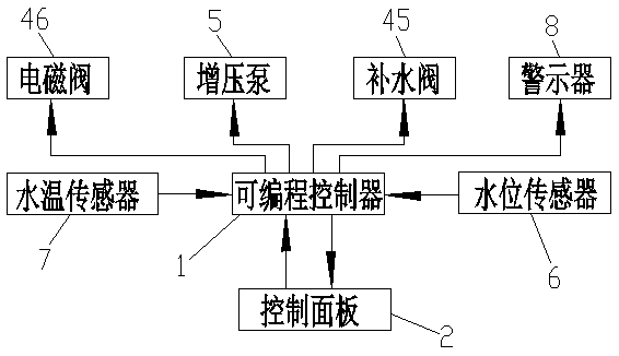
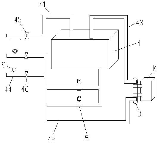
[0022] The reference signs are: air compressor K, programmable controller 1, control panel 2, cooler 3, hot water storage tank 4, water supply pipe 41, circulating water inlet pipe 42, circulating water return pipe 43, water supply pipe 44, Filling water valve 45, solenoid valve 46, booster pump 5, water level sensor 6, water temperature sensor 7, warning device 8.

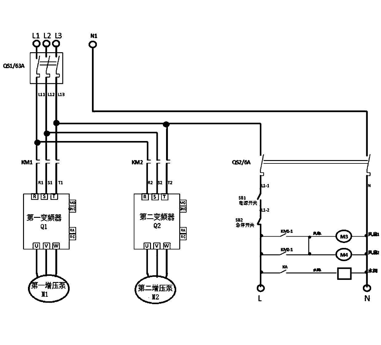
[0023] like Figure 1 to Figure 3 As shown, the present invention discloses a control system of an air compressor heat recovery device. The control system includes a programmable controller 1 arranged in a control circuit, an air compressor heat recovery device, a control panel 2 and a control cabinet. The programmable controller 1 is the core contr...


PUM


Abstract

The invention discloses an air compressor heat recovery device control system. The air compressor heat recovery device control system comprises a programmable controller, a control panel and a controlelectric cabinet of an automatic control air compressor heat recovery device. The air compressor heat recovery device comprises a cooler, a cyclic water route is connected with the cooler, the cyclicwater route comprises a heat storing water tank provided with a water supplementing pipe, a cyclic water inlet pipe, a cyclic water return pipe and booster pumps. The booster pumps are mounted in thecyclic water inlet pipe, and connected with a water supply pipe. The booster pumps comprise the first booster pump M1 and the second booster pump M2. A water supplementing valve is mounted on the water supplementing pipe, a water level sensor is mounted in the heat storing water tank, and water temperature sensors are mounted in the heat storing water tank, the cyclic water inlet pipe and the cyclic water return pipe correspondingly. The programmable controller controls the water supplementing valve and the booster pumps to be started up and shut down according to a command signal manually input from the control panel and a fedback water temperature signal and a water level signal in a programmed mode, the programmable controller is connected with a warning indicator, and an electromagnetic valve is mounted on the water supply pipe.

Description

technical field [0001] The invention relates to the technical field of heat recovery, in particular to the control technology of a heat recovery device of an air compressor, specifically the control system of the heat recovery device of an air compressor. Background technique [0002] The air compressor is one of the essential and important equipment in the machinery manufacturing industry, and its position in the machinery industry is the top priority. Now all the machinery industry is electrical integration. Now all the equipment in the machining industry, the gas pressure must be connected to the machine tool, and the high-precision testing equipment. The produced products need to be blown out of debris, moisture, etc. The gas compressed by the air compressor used is used in reality. If you want to use the air compressor to use the gas in other places, the air compressor will emit high heat, and you have to rely on oil to cool it down. Due to the high temperature, the he...

Claims


Application Information

Patent Timeline
Patent Type & Authority Applications(China)
IPC IPC(8): F04B39/00F04B39/06F04B49/06
CPCF04B39/00F04B39/06F04B49/065
Inventor 张祎李凯彭显卫万生旺谢峰杜志丹
Owner NINGBO XUNHUI ELECTRIC APPLIANCE
Why Eureka
Try Eureka