
High-gain Vivaldi array antenna loaded with director

An array antenna, high-gain technology, applied in the field of high-gain Vivaldi array antenna, can solve the problems of reducing antenna gain, distortion of radiation pattern, narrowing of impedance bandwidth, etc., achieve good impedance matching, increase antenna gain, and reduce transmission The effect of loss

Pending Publication Date: 2018-04-20
NANJING HOWKING COMM TECH
View PDF5 Cites 19 Cited by
  • Summary
  • Abstract
  • Description
  • Claims
  • Application Information

AI Technical Summary

Problems solved by technology

[0003] Traditional antenna arrays generally use a feed network based on a microstrip or stripline structure. In the millimeter wave frequency band, the microstrip line will generate radiation that cannot be ignored, so the energy transmission efficiency is not high; the stripline structure Although the feed network overcomes this shortcoming, its feed network is more complicated, so the processing cost is relatively high
According to the radiation principle of the Vivaldi antenna, the antenna is composed of a narrow slot line at one end and a wider slot line at the other end. The slot line transition is exponentially changing, and different parts of it radiate electromagnetic waves of different frequencies. Therefore, to achieve a wider Impedance bandwidth, the length of the Vivaldi radiating element should be increased accordingly, which will cause a certain degree of coupling phenomenon between different positions of the radiating patch, resulting in phase inversion, distorting the radiation pattern and reducing the antenna gain
And reducing the length of the Vivaldi radiation unit will make the resonance point at the low frequency move to the high frequency direction, narrowing the impedance bandwidth

Method used


Image

  • High-gain Vivaldi array antenna loaded with director
  • High-gain Vivaldi array antenna loaded with director
  • High-gain Vivaldi array antenna loaded with director

Examples


Embodiment Construction

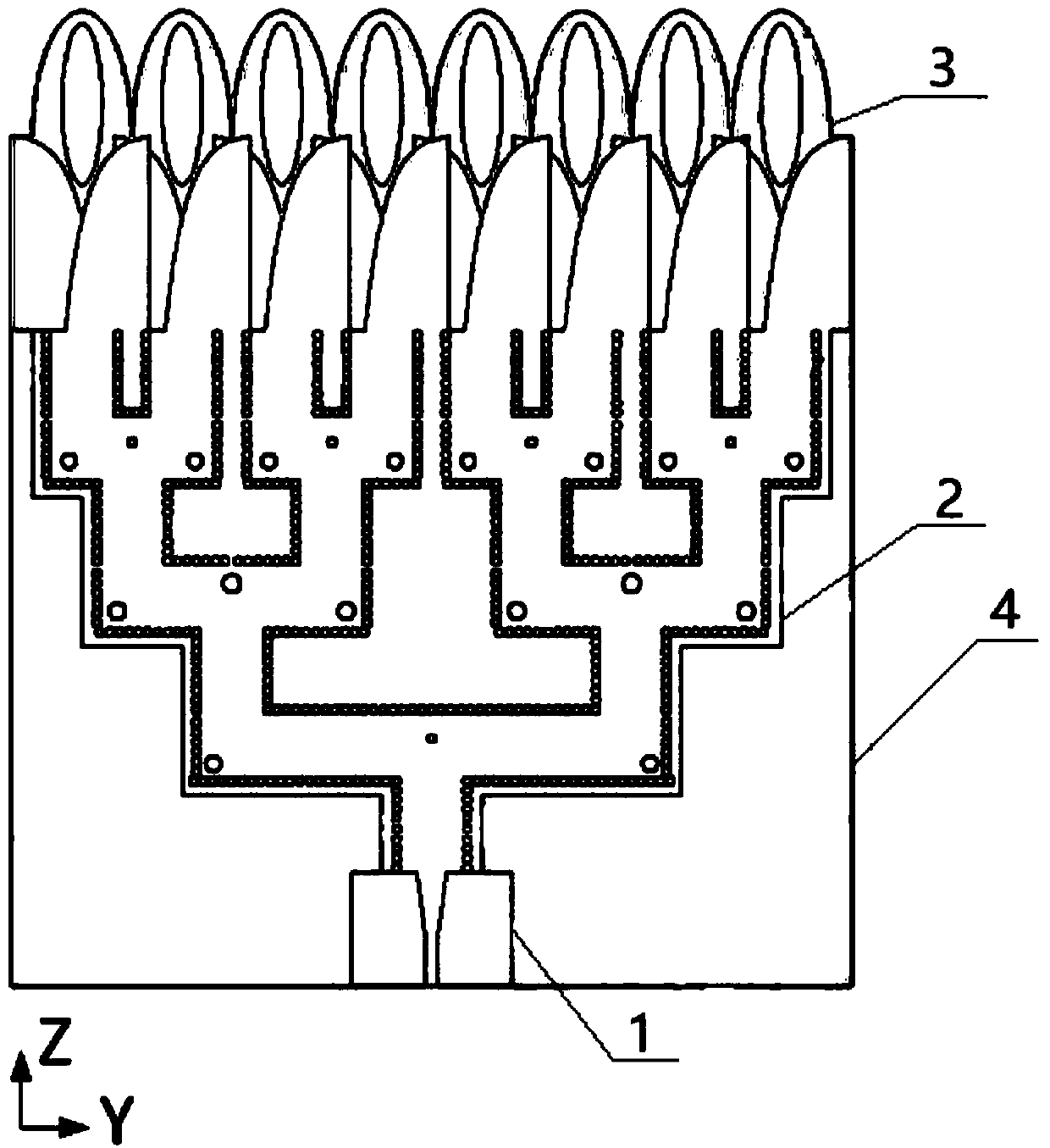
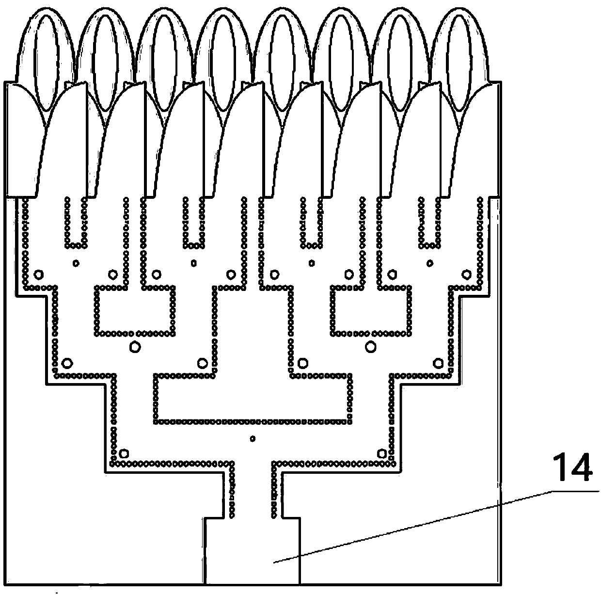
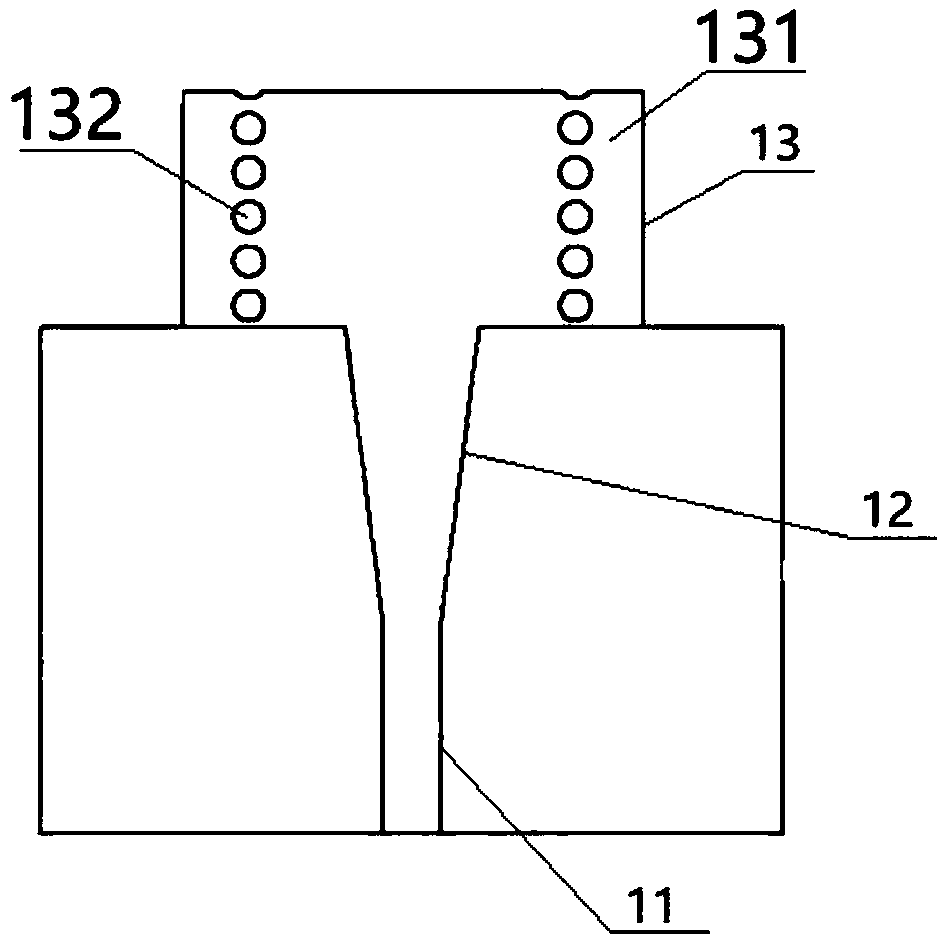
[0026] Such as Figure 1-5 As shown, the present invention discloses a high-gain Vivaldi array antenna loaded with a director, including a microstrip SIW conversion structure 1, a SIW-based one-point eight-way power divider 2 and eight Vivaldi antenna units 3, and the microstrip SIW conversion Structure 1 converts the fed-in electromagnetic waves into electromagnetic waves in the SIW transmission section, and the SIW-based one-to-eight power divider 2 uniformly transmits the electromagnetic waves in the SIW transmission section to eight Vivaldi antenna units 3, and the microstrip SIW conversion structure 1 includes microstrip Line 11, trapezoidal microstrip gradient line 12 and SIW transmission section 13, microstrip line 11 and SIW transmission section 13 are connected through trapezoidal microstrip gradient line 12, and the one-point eight-way power divider 2 based on SIW includes metal layer 21 and inductive metal Through hole 22, Vivaldi antenna unit 3 includes Vivaldi rad...


PUM

PropertyMeasurementUnit
Thicknessaaaaaaaaaa

Abstract

The invention relates to the technical field of antennas, and particularly relates to a high-gain Vivaldi array antenna loaded with a director. The high-gain Vivaldi array antenna comprises a microstrip SIW conversion structure, an SIW-based one-to-eight power divider and eight Vivaldi antenna units. The microstrip SIW conversion structure converts the electromagnetic waves fed in by a microstripline into the electromagnetic waves of the SIW transmission band. The microstrip SIW conversion structure comprises the microstrip line, a trapezoid microstrip transition line, a metal ground and theSIW transmission band. The SIW-based one-to-eight power divider comprises a metal layer and inductive metal through holes. Each Vivaldi antenna unit comprises a Vivaldi radiation unit, an elliptical metal patch and a semi-elliptical dielectric substrate. The 39.5-46GHz frequency band can be covered and more than 1dB of the antenna gain can be enhanced within the frequency band coverage on the basis of the original array antennas.

Description

technical field [0001] The invention relates to the technical field of antennas, in particular to a high-gain Vivaldi array antenna loaded with a director. Background technique [0002] Millimeter wave technology can realize ultra-high-speed wireless data transmission by increasing the spectrum bandwidth, thus becoming one of the key technologies in 5G communication. As a linearly polarized traveling wave antenna, the Vivaldi antenna proposed in the 1970s has the characteristics of broadband, high gain, and low cross-polarization, and has been widely used in communications, electronic countermeasures, and other fields. With the development of planar integrated circuits, printed Vivaldi antenna arrays with low cost, simple structure, and easy processing have attracted extensive attention from scholars. Applying the Vivaldi array antenna to the millimeter wave frequency band is a current research hotspot. [0003] Traditional antenna arrays generally use a feed network based...

Claims


Application Information

Patent Timeline
IPC IPC(8): H01Q1/50H01Q21/00H01Q1/52H01Q19/06H01Q1/36H01Q1/38
CPCH01Q1/36H01Q1/38H01Q1/50H01Q1/523H01Q19/06H01Q21/0006
Inventor 陈平朱晓维刘鹏飞李晨枫
Owner NANJING HOWKING COMM TECH
Learn More