A crimping structure with multi-level thyristors connected in series

A technology of thyristor and connection structure, applied in the direction of semiconductor/solid-state device components, semiconductor devices, electrical components, etc., can solve the problem of not meeting the pressing force requirements of larger-sized thyristors, not completely limiting the degree of freedom of the radiator, and not being able to precisely control The size of the pressing force and other issues can achieve good heat dissipation effect and flow effect, ensure good contact, and the effect of simple pressure method.

Active Publication Date: 2019-01-18
CHINA XD ELECTRIC CO LTD
View PDF3 Cites 0 Cited by
  • Summary
  • Abstract
  • Description
  • Claims
  • Application Information

AI Technical Summary

Problems solved by technology

[0004] The compression force provided by the above two thyristor crimping structures is relatively limited, which cannot meet the compression force requirements of larger thyristors that are gradually emerging.
The problems of the first type of thyristor crimping structure are: 1) The radiator is suspended on the epoxy resin boards on both sides by springs, and the center of the radiator cannot be positioned accurately, resulting in uneven stress on the thyristor
2) The pressing force is applied to the thyristor by rotating the top pressure bolt, which cannot accurately control the size of the pressing force
Affect the life of the thyristor
Among them, there are problems in the second crimping method: 1) In order to solve the positioning problem of the radiator, a variety of parts are introduced, and the structure is complicated
2) The top pressure rod with a ball head and the pressure plate with a spherical groove cannot completely limit the degree of freedom of the radiator in contact with it, and will bring longitudinal dynamic load to the thyristor under the action of vibration during equipment operation. It is not conducive to the uniform stress of the thyristor

Method used


Image

  • A crimping structure with multi-level thyristors connected in series
  • A crimping structure with multi-level thyristors connected in series
  • A crimping structure with multi-level thyristors connected in series

Examples


Embodiment Construction

[0025] The present invention will be described in further detail below in conjunction with the accompanying drawings and specific embodiments, but not as a limitation of the present invention.

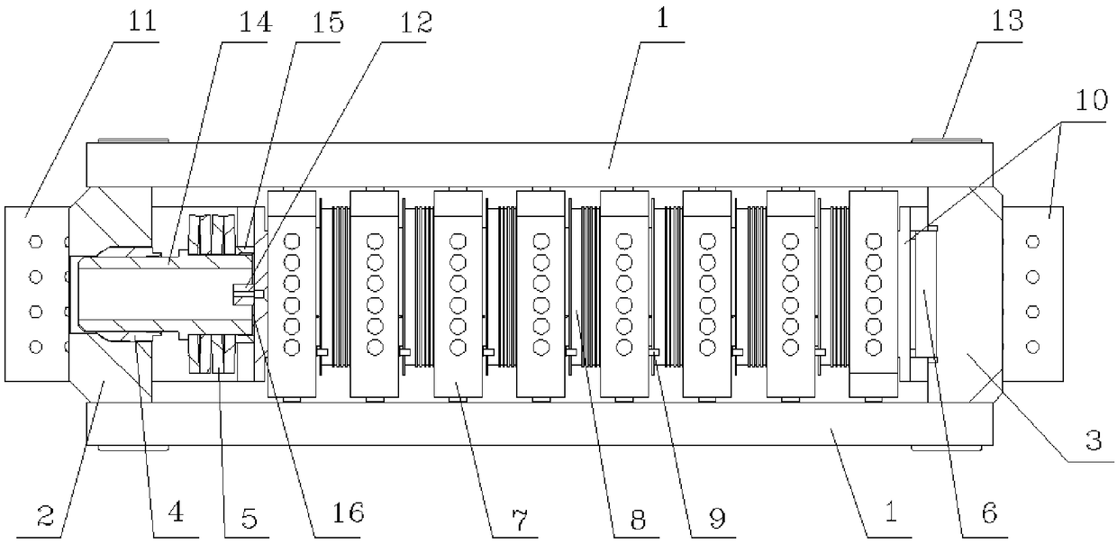
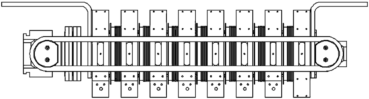
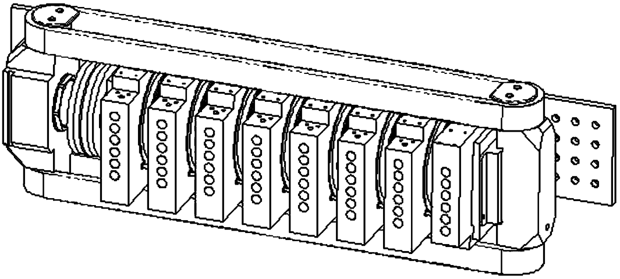
[0026] The multilevel thyristor crimping structure of the present invention, its front view is as follows figure 1 As shown, the top view is as figure 2 As shown, the 3D view is as image 3 as shown,

[0027] The two insulating pull rings 1 arranged up and down and the left yoke 2 and right yoke 3 connected to the two insulating pull rings 1 form the external frame of the crimping structure. The multi-stage thyristor crimping structure consists of crimping thyristors 8 and radiators 7 Phases are connected in series to form the entire silicon stack unit. The two ends of the silicon stack unit are respectively connected to the left output bus bar 11 and the right output bus bar 10, and then installed between the left yoke 2 and the right yoke 3 through the pressure unit arranged at on...


PUM


Abstract

The invention provides a crimping structure with the series connection of thyristors of multiple stages. An external frame of the crimping structure is formed by two insulating pull rings and a left yoke and a right yoke connected to the two insulating pull rings. A silicon stack unit is formed by the series connection of multiple heat radiators and multiple thyristors alternately. The silicon stack unit is installed between the left yoke and the right yoke through a pressure unit arranged at one end. The insulating pull rings can provide pressing force with a larger range than that of an existing tensioning device, the good contact between the thyristors and the heat radiators is ensured, thus the thyristors get good heat dissipation effect and through-flow effect, the press mounting requirements of thyristors with larger sizes and more stages can be satisfied. The crimping structure of the present invention has the advantages of compactness, a small number of components, simple assembly and convenient maintenance.

Description

【Technical field】 [0001] The invention relates to a method and a device for assembling high-power electric electronic devices in a power system, in particular to a crimping structure of multi-level thyristors connected in series. 【Background technique】 [0002] Thyristor (Thyristor) is a high-power semiconductor device that can work under high voltage and high current conditions. Its appearance has expanded semiconductor devices from the field of weak current to the field of strong current. In recent years, it has been widely used in the field of high-voltage direct current transmission. With the continuous development and updating of high-voltage direct current transmission technology and the improvement of power transmission level, large-size thyristors have emerged as the times require. As the size of the thyristor increases, greater pressing force is required to ensure good contact between the thyristor and the heat sink when multi-level thyristors are assembled in serie...

Claims


Application Information

Patent Timeline
Patent Type & Authority Patents(China)
IPC IPC(8): H01L23/40
CPCH01L23/4006H01L23/4012H01L2023/4025H01L2023/4087
Inventor 苟锐锋李志强张雷娄彦涛杨晓平王英洁宋双祥
Owner CHINA XD ELECTRIC CO LTD
Why Eureka
Try Eureka