Digital frequency demodulation phase noise measuring device and method

A phase noise, measurement device technology, applied in the direction of noise figure or signal-to-noise ratio measurement, etc., can solve the problems of long measurement time, long delay time of analog delay line, low efficiency, etc., achieve good near-end phase noise measurement sensitivity, realize The effect of simple scheme and simple system structure

Inactive Publication Date: 2018-04-27
THE 41ST INST OF CHINA ELECTRONICS TECH GRP
View PDF10 Cites 20 Cited by
  • Summary
  • Abstract
  • Description
  • Claims
  • Application Information

AI Technical Summary

Problems solved by technology

[0005] 1. When the power of the source to be measured is lower than the ideal power, the fixed IF gain will reduce the carrier power of the source to be measured after quantization compared with the noise power, thereby reducing the dynamic range of phase noise measurement; when the power of the source to be measured is higher than the ideal power When , the fixed IF gain may cause ADC saturation, resulting in wrong measurement results;
[0006] 2. Limited by the principle of frequency discrimination, the maximum analysis frequency deviation is proportional to the reciprocal of the delay time, and the sensitivity is proportional to the delay time. Ther

Method used


Image

  • Digital frequency demodulation phase noise measuring device and method
  • Digital frequency demodulation phase noise measuring device and method
  • Digital frequency demodulation phase noise measuring device and method

Examples


Embodiment 1

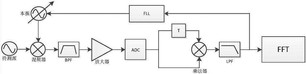
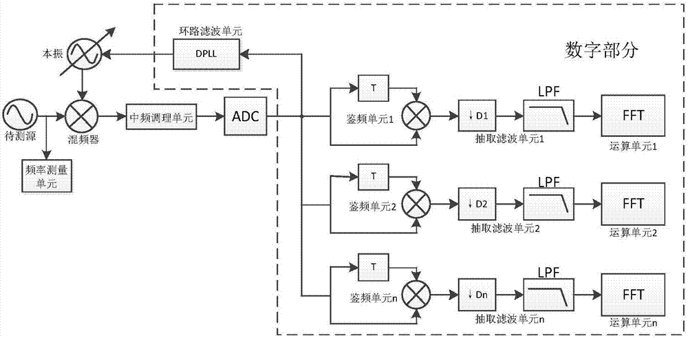
[0058] Such as figure 2 A phase noise measurement device for digital frequency discrimination as shown, including a frequency measurement unit, a local oscillator unit, a frequency mixing unit, an intermediate frequency conditioning unit, an ADC unit, and a digital processing unit;

[0059] The frequency measurement unit is configured to measure the carrier frequency of the source to be tested through the microwave frequency division link and the FPGA, providing a basis for the preset local oscillator;

[0060] The local oscillator unit is configured to provide a local oscillator signal for the frequency mixing unit, which has a DC frequency modulation function. When the loop is phase-locked, it can track the frequency change of the source under test and form a fixed intermediate frequency difference with the source under test. ;

[0061] a frequency mixing unit configured to mix the frequency signal generated by the source to be measured with the local oscillator signal gen...

Embodiment 2

[0082] On the basis of the above-mentioned embodiments, the present invention also mentions a phase noise measurement method of digital frequency discrimination, which is realized by the above-mentioned phase noise measurement device of digital frequency discrimination, and the specific steps are as follows:

[0083] Step 1: Use the frequency measurement unit to measure the carrier frequency f of the source to be tested;

[0084] Step 2: Set the local oscillator frequency according to the measured value of the carrier frequency generated in step 1, so that the difference between the local oscillator frequency and the frequency of the source to be measured is fixed and the beat frequency is fixed;

[0085] Step 3: Utilize the loop filter unit to detect the peak value Ap and the valley value Av of the beat frequency signal, and calculate the amplitude A of the beat frequency signal according to formula (1);

[0086] A=(Ap+Av) / 2 (1);

[0087] Step 4: Use formula (2) to calculate...


PUM


Abstract

The invention discloses a digital frequency demodulation phase noise measuring device and method and belongs to the electronic measurement technology field. A digital phase-locked loop is utilized torealize carrier frequency tracking and phase locking of a to-be-measured source, an intermediate frequency amplifying unit is utilized to realize adaptive adjustment, an original digital frequency demodulation unit is utilized to extract noise, and plural average of the frequency domain is utilized to improve the phase noise measurement sensitivity of a system. The method is advantaged in that when phase noise measurement can be realized through the frequency demodulation method, compatibility of frequency offset and sensitivity indexes is analyzed, and the better near-end phase noise measurement sensitivity can be realized; the realization scheme is simple, system configuration is concise, the technology is relatively mature, realization cost is low, and the cost performance advantage isrealized to a certain degree.

Description

technical field [0001] The invention belongs to the technical field of electronic measurement, and in particular relates to a digital frequency discrimination phase noise measurement device and method. Background technique [0002] Phase noise is an important index to measure the short-term frequency stability of a signal source, and it has an important impact on the performance of an electronic system. For example, in the radar T / R component, the phase noise of the local oscillator will affect the radar detection distance. In the communication system, the phase noise of the carrier will cause adjacent channel interference and demodulation errors. In the satellite navigation system, the phase of the uplink and downlink carriers Noise will affect the design cost and resource occupation of satellite payloads. The phase noise indicators of these electronic system signal sources are getting higher and higher. At the same time, in order to improve the target resolution and commun...

Claims


Application Information

Patent Timeline
IPC IPC(8): G01R29/26
Inventor 朱伟杜念文李伟刘强毛黎明
Owner THE 41ST INST OF CHINA ELECTRONICS TECH GRP
Why Eureka
Try Eureka