
Fluorine salt test system and method based on molten salt rector passive residual heat removal system

A technology of waste heat removal system and experimental system, which is applied in the field of passive waste heat removal system of molten salt reactor, can solve problems such as the fluorine salt circuit experimental method not involved in the overall design of the fluorine salt experimental circuit, the design method of the fluorine salt experimental circuit, etc. , to achieve the effect of ensuring the stability of

Active Publication Date: 2018-05-04
XI AN JIAOTONG UNIV
View PDF8 Cites 9 Cited by
  • Summary
  • Abstract
  • Description
  • Claims
  • Application Information

AI Technical Summary

Problems solved by technology

This system is safe, reliable, and easy to operate, but it is only suitable for sodium with a low melting point and less corrosiveness, and it is no longer suitable for fluorine salts with special corrosiveness and high melting point
[0004] Another example is the Chinese patent CN103280247A which provides a passive waste heat removal system for fluorine-salt cooling high-temperature reactors, which mainly includes an air cooling tower, a molten salt pool, a support ring, a splitter plate, and a heat exchanger. The exchanger takes away the waste heat of the reactor, but the system does not involve the overall design of the fluoride salt experimental circuit and the experimental method of the fluorine salt circuit. In addition, the Chinese patent CN105788674A provides a new passive waste heat removal system for molten salt reactors based on high-temperature heat pipes , the system also only designs the concept of passive waste heat removal system, and does not mention the design method of the fluoride salt experimental circuit

Method used


Image

  • Fluorine salt test system and method based on molten salt rector passive residual heat removal system

Examples


Embodiment Construction

[0028] Below in conjunction with accompanying drawing and specific embodiment the present invention is described in further detail:

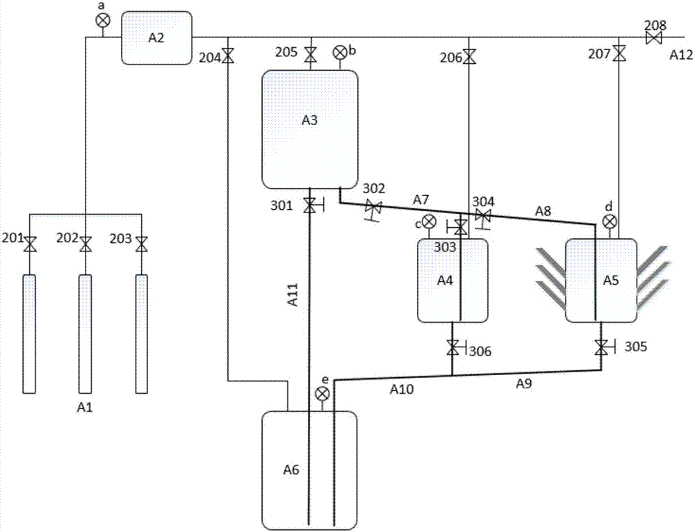
[0029] Such as figure 1 As shown, before the start of the experiment, the argon auxiliary system was used to check the tightness of the system, and the first argon valve 201, the second argon valve 202, and the third argon valve 203 were slowly opened, and the reading of the pressure gauge a rose. a After the reading is stable, open the fourth argon valve 204, the fifth argon valve 205, the sixth argon valve 206, and the seventh argon valve 207 to simulate the core tank A3, the control tank A4, the heat pipe tank A5 and the storage tank The readings of pressure gauges b, c, d and e on A6 rise, and the readings of all pressure gauges do not change significantly after a period of time, indicating that the system is well sealed. Close the first argon valve 201, the second argon valve 202 and the third argon valve 203, slowly open the eighth argon ...


PUM


Abstract

The invention discloses a fluorine salt test system and a method based on a molten salt rector passive residual heat removal system. The fluorine salt test system comprises an argon gas assist systemformed of a argon gas bottle, a buffer tank, a argon gas pipe and a valve on the pipe, a storage tank used for storing fluorine salt for a long time, a simulated core tank used for simulating the relative position of the molten salt rector core, a heat pipe can with the quick heat radiation effect, a contrast tank used for playing a contrast effect on the heat pipe can and a fluorine salt pipe system connecting fluorine salt pipes of fluorine salt tank with the valve. The invention also provides the test method of the test system, which comprises the following steps: heating the fluorine saltin the storage tank into liquid state, entering the simulated core tank through the fluorine salt pipe under the pressure difference of the argon gas, flowing into the contrast tank or the heat pipe can to perform test under the action of the gravity, and finally flowing back to the storage tank along the fluorine salt pipes. The fluorine salt test system provided by the invention can bear high-temperature work condition, the test process operation is simple and the system loop is safe and reliable.

Description

technical field [0001] The invention relates to the technical field of molten salt reactor passive waste heat discharge system, in particular to a fluoride salt experiment system and method based on the molten salt reactor passive waste heat discharge system. Background technique [0002] With the development of new-type molten salt reactors, related molten salt experiments are also being carried out in full swing. Fluoride salts are generally used as coolants for molten salt reactors in the world, so fluoride salts are used in relevant experimental research. At present, there are very few experiments on fluoride salts in the world, and the relevant experimental data of fluoride salts is extremely scarce, so it is particularly important to build a large-scale experimental bench. The circuit design of the fluoride salt experiment plays a vital role in the smooth development of the experiment. A good design scheme can not only save costs, but also an important guarantee for th...

Claims


Application Information

Patent Timeline
IPC IPC(8): G21C17/00
CPCG21C17/001Y02E30/30
Inventor 张大林周健成刘明皓王成龙田文喜苏光辉秋穗正
Owner XI AN JIAOTONG UNIV
Learn More