A waste compression station energy-saving control system

A technology of energy-saving control system and garbage compression station, which can be applied in the directions of fluid pressure actuation system components, fluid pressure actuation system testing, garbage collection, etc. The effect of reducing power loss, reducing power consumption, avoiding loss

Active Publication Date: 2020-05-05
JINLV ENVIRONMENT TECH
View PDF3 Cites 0 Cited by
  • Summary
  • Abstract
  • Description
  • Claims
  • Application Information

AI Technical Summary

Problems solved by technology

[0004] The object of the present invention is to provide a kind of energy-saving control system of the garbage compression station, to solve the above-mentioned background technology, the stage of the maximum power consumption in the working process of the garbage compression station is the pressure-holding stage, if the power consumption of this stage is reduced, then good performance can be achieved. The energy-saving effect; secondly, during this process, the stroke of the oil cylinder remains basically unchanged, and the system is in an overflow state, resulting in a waste of energy, and at the same time, a large amount of heat is generated, which makes the oil temperature too high and the hydraulic system fails frequently.

Method used


Image

  • A waste compression station energy-saving control system
  • A waste compression station energy-saving control system
  • A waste compression station energy-saving control system

Examples


Embodiment Construction

[0023] The following will clearly and completely describe the technical solutions in the embodiments of the present invention with reference to the accompanying drawings in the embodiments of the present invention. Obviously, the described embodiments are only some, not all, embodiments of the present invention. Based on the embodiments of the present invention, all other embodiments obtained by persons of ordinary skill in the art without making creative efforts belong to the protection scope of the present invention.

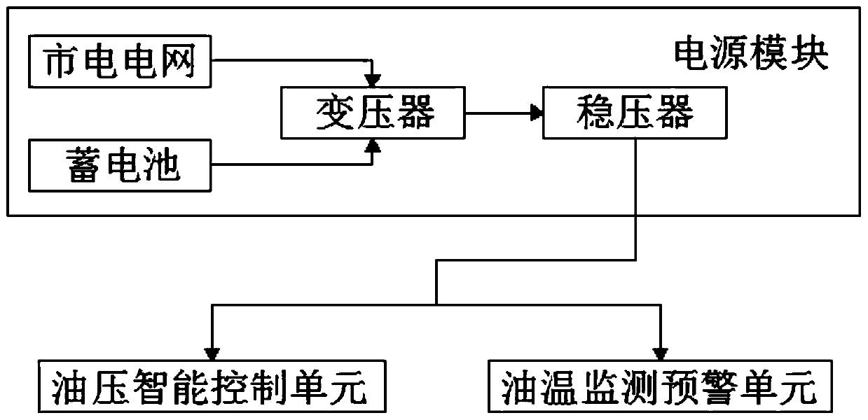
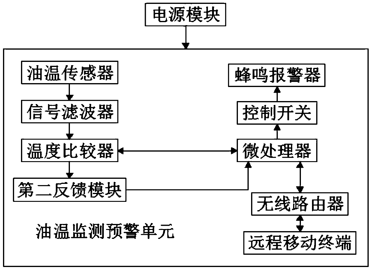
[0024] see Figure 1-3 , the present invention provides a technical solution: an energy-saving control system for a garbage compression station, including a power supply module, an oil pressure intelligent control unit, and an oil temperature monitoring and early warning unit. The input terminal connection of the warning unit.

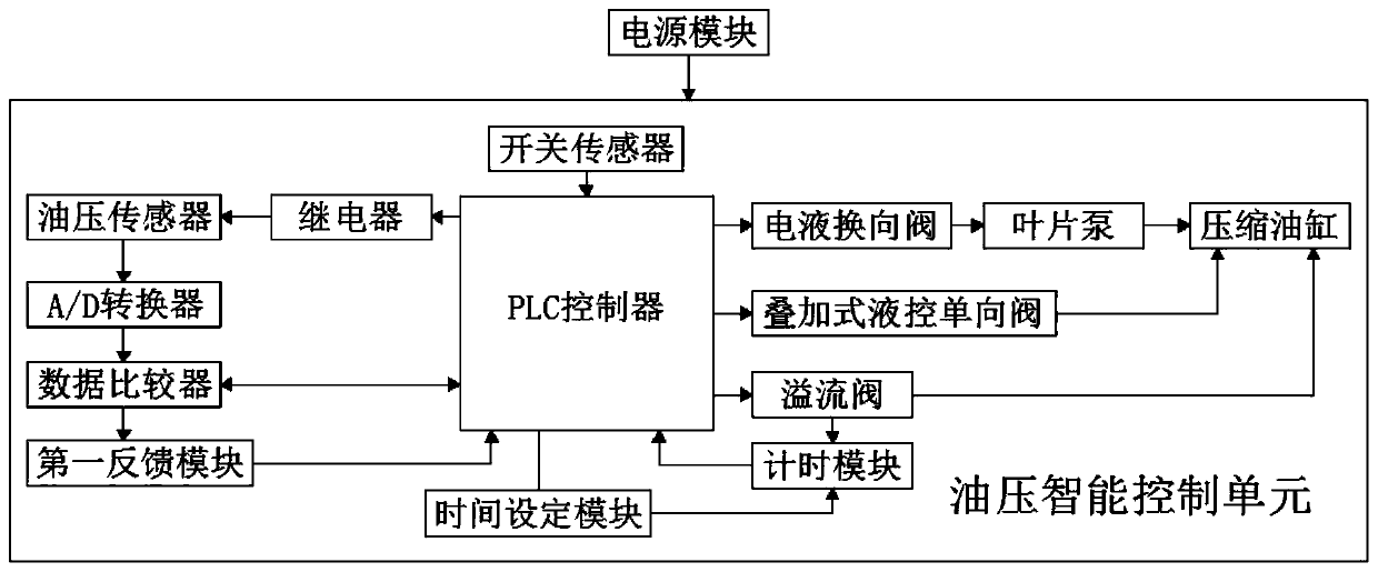
[0025] The oil pressure intelligent control unit includes a PLC controller, and the input end of the PLC controller is connected to ...


PUM


Abstract

The invention discloses an energy-saving control system of a garbage compression station. The energy-saving control system comprises a power source module, an oil pressure intelligent control unit andan oil temperature monitoring and pre-warning unit. The output end of the power source module is connected with the input end of the oil pressure intelligent control unit and the input end of the oiltemperature monitoring and pre-warning unit. The oil pressure intelligent control unit comprises a PLC, the input end of the PLC is connected with the output end of a switch sensor, the output end ofthe PLC is connected with the control end of an oil pressure sensor through a relay, the output end of the oil pressure sensor is connected with the input end of a data comparator through an A / D transverter, and the data comparator is in bi-directional signal connection with the PLC. According to the energy-saving control system of the garbage compression station, an electro-hydraulic directionalcontrol valve is controlled by the PLC, a vane pump can supply oil to a rodless cavity of a compression oil cylinder, pressure maintenance of the rodless cavity of the compression oil cylinder is achieved through the PLC and an overlap-type hydraulic control one-way valve, and energy saving and consumption reduction of the equipment are achieved.

Description

technical field [0001] The invention relates to the technical field of energy-saving control of garbage compression stations, in particular to an energy-saving control system of garbage compression stations. Background technique [0002] The garbage compression station is a device that compresses garbage by pushing the pressure head through a hydraulic cylinder. The rubbish compression process of the pressure head is divided into four stages: the rapid advance stage of the pressure head (light load stage, the pressure of the hydraulic system is low, about 4 seconds) → the compression stage (heavy load stage, the pressure of the hydraulic system is high, about 5 seconds) → maintenance Pressure stage (extremely heavy load stage, hydraulic system overflow, about 5 seconds) → pressure head return stage (light load stage, hydraulic system pressure is low, about 5 seconds). [0003] To sum up: the stage with the largest power consumption in the working process of the garbage comp...

Claims


Application Information

Patent Timeline
Patent Type & Authority Patents(China)
IPC IPC(8): F15B21/08F15B11/08F15B13/02F15B19/00F15B1/02B65F9/00
CPCB65F9/00F15B1/02F15B11/08F15B13/024F15B19/00F15B21/04F15B21/087
Inventor 郑磊黄大智
Owner JINLV ENVIRONMENT TECH
Why Eureka
Try Eureka