Tangential driving double-difference butterfly-wing silicon microgyroscope and application method thereof

A silicon micro-gyroscope and butterfly-wing technology, which is applied in the direction of speed measurement by gyro effect, gyroscope/steering sensing equipment, measuring device, etc., can solve the problems of low stability and poor adaptability, and increase mechanical sensitivity and sensitivity Improve and reduce the effect of supporting energy loss

Active Publication Date: 2018-05-11
NAT UNIV OF DEFENSE TECH
View PDF8 Cites 13 Cited by
  • Summary
  • Abstract
  • Description
  • Claims
  • Application Information

AI Technical Summary

Problems solved by technology

The traditional butterfly-wing micro-gyro sensitive structure has a driving mode and a detection mode. In the structural design, when the detection mode of the micro-gyroscope coincides with t...

Method used


Image

  • Tangential driving double-difference butterfly-wing silicon microgyroscope and application method thereof
  • Tangential driving double-difference butterfly-wing silicon microgyroscope and application method thereof
  • Tangential driving double-difference butterfly-wing silicon microgyroscope and application method thereof

Examples


Embodiment Construction

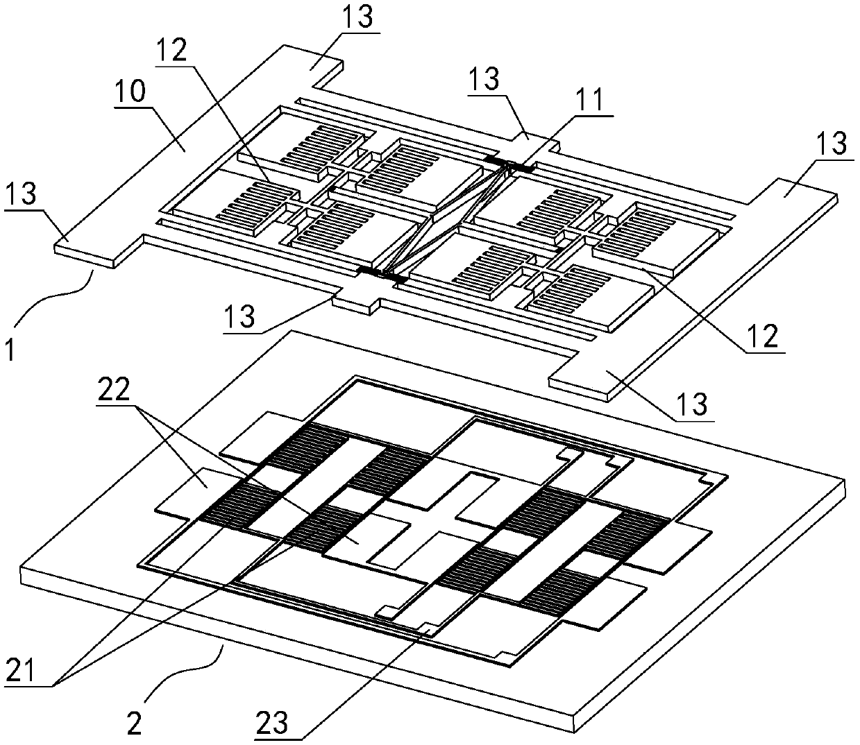
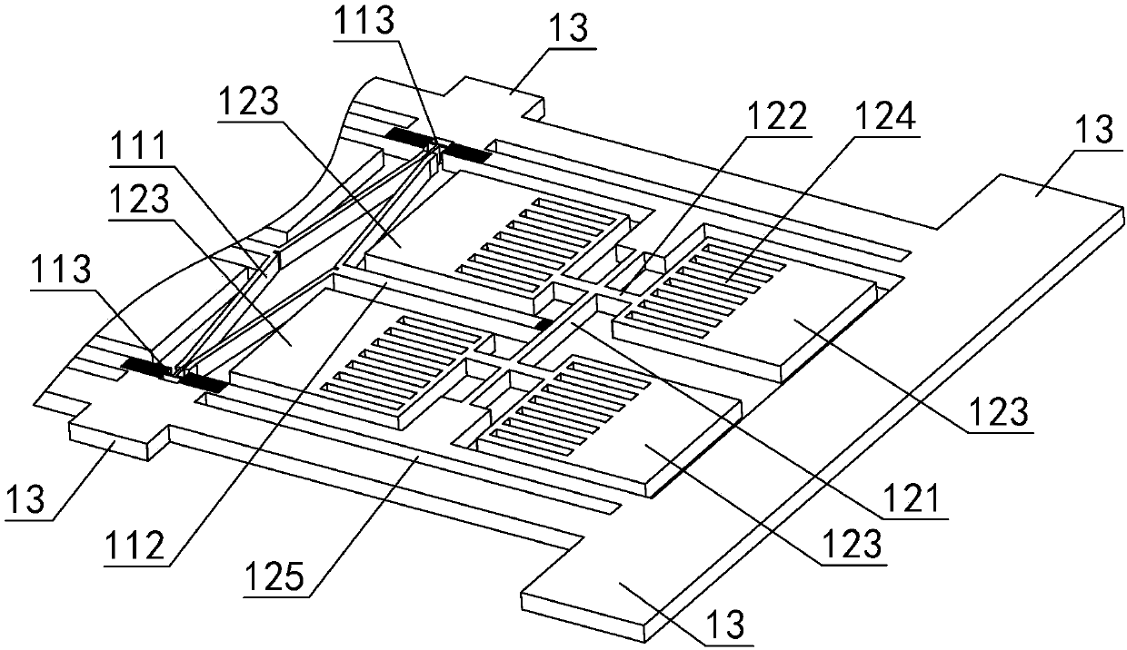
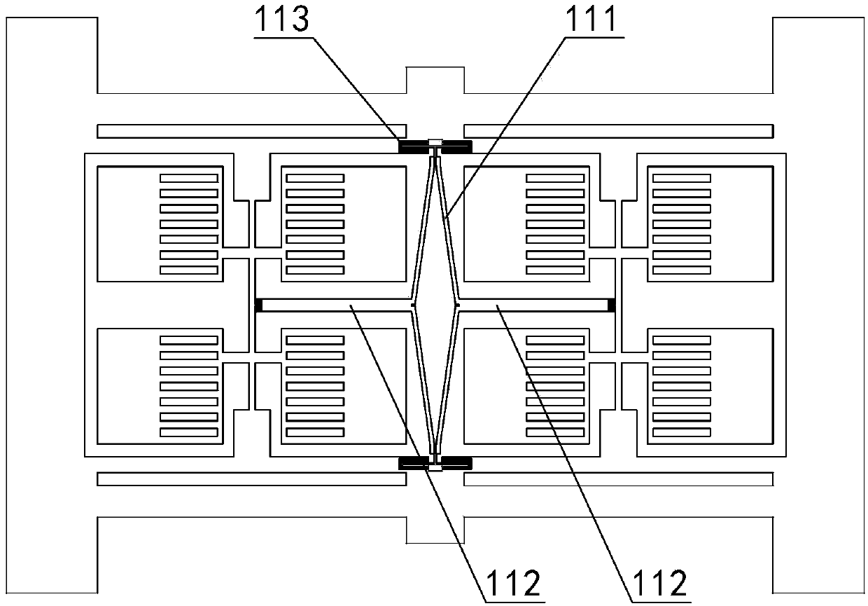
[0045] Such as figure 1 with figure 2 As shown, the tangentially driven double-differential butterfly-wing silicon microgyroscope of this embodiment includes a silicon-glass double-layer structure composed of a silicon sensitive structure 1 and a glass electrode plate 2. The silicon sensitive structure 1 includes an external frame 10, and the external frame 10 There is a coupling spring structure 11 and two silicon-sensitive substructures 12 connected through the coupling spring structure 11. The two silicon-sensitive substructures 12 are symmetrically arranged relative to the coupling spring structure 11. The silicon-sensitive substructure 12 includes a support beam 121 and a The cantilever beam 122 is connected to the four inertial mass blocks 123 on the support beam 121, the inertial mass block 123 is provided with evenly distributed drive combs 124, and the glass electrode plate 2 is provided with drive electrodes 20, detection electrodes 21 and electrode pads 22. The dr...


PUM


Abstract

The invention discloses a tangential driving double-difference butterfly-wing silicon microgyroscope and an application method thereof. The silicon microgyroscope is of a silicon-glass double-layer structure which is constituted by a silicon sensitive structure and a glass electrode plate, the silicon sensitive structure comprises an external framework, an internal coupling spring structure and two silicon sensitive subsidiary structures, each silicon sensitive subsidiary structure comprises four inertial mass blocks which are connected to a supporting beam through a cantilever beam, driving comb teeth are arranged on the inertial mass blocks, a driving electrode, a detecting electrode and an electrode welding disc are arranged on the glass electrode plate, and detecting capacitors of thetwo silicon sensitive subsidiary structures constitute a double-difference slab detecting capacitor. The application method comprises the step of additionally applying static electrostatic stiffness to a unilateral silicon sensitive structure to change a modal control method of the system modal frequency. By means of the tangential driving double-difference butterfly-wing silicon microgyroscope and the application method thereof, the limit of normal displacement on driving amplitude and capacitive gaps can be effectively removed, the driving Q value can be effectively increased, the working state of the gyroscope is improved, thus the sensitivity of the gyroscope is improved, the bandwidth of the gyroscope is increased, and the stability of the gyroscope is improved.

Description

technical field [0001] The invention relates to micromechanical sensor technology in microelectromechanical systems, in particular to a tangentially driven double-differential butterfly-wing silicon microgyroscope and an application method thereof. Background technique [0002] Compared with traditional mechanical gyroscopes, micro-mechanical gyroscopes based on MEMS technology have outstanding advantages such as small size, light weight, low cost, and high reliability, and have been more and more widely used in various fields. Take the butterfly-wing silicon micro-gyroscope as an example. It is a capacitive micro-electro-mechanical gyroscope based on the Coriolis effect, which adopts the working mode of electrostatic drive and capacitance detection. The traditional butterfly-wing micro-gyroscope was first proposed by the Swedish IMEGO Institute. Its sensitive structure is a four-mass fully differential structure, which uses anisotropic wet etching of single crystal silicon ...

Claims


Application Information

Patent Timeline
IPC IPC(8): G01C19/5656
CPCG01C19/5656
Inventor 肖定邦吴学忠侯占强周剑卓明徐强徐向明李文印
Owner NAT UNIV OF DEFENSE TECH
Why Eureka
Try Eureka