Design method of V-shaped beam mask plate

A design method and mask technology, applied in optics, optical components, instruments, etc., can solve the problems of difficult adjustment of experimental light path, difficult industrial production, etc., achieve important application prospects, and simplify the effect of light path structure

Active Publication Date: 2018-05-15
HENAN UNIV OF SCI & TECH
View PDF5 Cites 4 Cited by
  • Summary
  • Abstract
  • Description
  • Claims
  • Application Information

AI Technical Summary

Problems solved by technology

However, this optical path requires two laser beams to be coupled, which brings difficulties to the adjustment of the experimental optical path and is diffi

Method used


Image

  • Design method of V-shaped beam mask plate
  • Design method of V-shaped beam mask plate
  • Design method of V-shaped beam mask plate

Examples


Embodiment Construction

[0022] The present invention will be further described in detail below in conjunction with the accompanying drawings and specific embodiments.

[0023] A method for designing a mask plate of a V-shaped light beam, comprising the following steps:

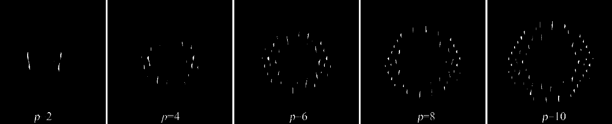
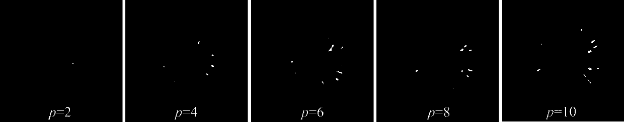
[0024] Step 1. Based on the accurate orthogonal solution of the spatial paraxial wave equation in the elliptical coordinate system, an electric field expression Vpε of a V-shaped beam is derived;

[0025] Step 2: Calculate the angle function for the electric field expression Vpε, get angle(Vpε), and compare it with the blazed grating P 0 Combine to get angle(Vpε)+P 0 , where the blazed grating P 0 The phase expression of is:

[0026] P 0 =2πx / d, where d is the period of the blazed grating;

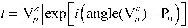
[0027] Step 3, using the principle of computational holography to obtain the specific expression of the complex transmittance function of the mask plate of the V-shaped beam through computer coding:

[0028]

[0029] Among them, |·| mean...


PUM


Abstract

The invention discloses a design method of a V-shaped beam mask plate. The method comprises the following steps: (1) derivating an electric field expression formula Vpepsilon of a V-shaped beam basedon an accurate orthogonality solution of a space paraxial wave equation in an oval coordinate system; (2) solving an angular function by virtue of the electric field expression formula Vpepsilon, so as to obtain angle(Vpepsilon), and combining with blazed grating P0, so as to obtain angle(Vpepsilon)+P0; and (3) carrying out computer coding by virtue of a computer-generated holography principle, soas to obtain a specific expression formula (shown in the description) of a re-transmittance function of the V-shaped beam mask plate, wherein a mask plate described by the re-transmittance function is the V-shaped beam mask plate. The mask plate disclosed by the invention is capable of emitting a V-shaped beam including V-shaped pedals; the number of the V-shaped pedals can be controlled and is twice of an order p; the optical structure is remarkably simplified; and therefore, the mask plate has very important application prospects in a cell sorting technique.

Description

technical field [0001] The invention relates to the fields of particle manipulation and quantum information coding, in particular to a method for designing a V-shaped light beam mask. Background technique [0002] With the continuous development of laser technology, phase-structured beams have become a research hotspot in the field of spatially structured light fields, and are widely used in quantum information coding, particle sorting and control, optical super-resolution, and optical image processing. Among them, the Ince-Gaussian (IG) beam has a unique advantage in the research work in the field of particle manipulation due to the diversity of its spatial mode distribution. [0003] On the other hand, regarding the sorting of microparticles, researchers have done a lot of research, but mainly focused on fluorescence activated cell sorting and pure optical cell sorting. In 1999, Anne Y.Fu and others studied a miniature fluorescence-activated cell sorter that has the advan...

Claims


Application Information

Patent Timeline
IPC IPC(8): G02B27/00G02B27/09
CPCG02B27/0012G02B27/0911G02B27/0944
Inventor 台玉萍张浩李新忠李贺贺唐苗苗王静鸽
Owner HENAN UNIV OF SCI & TECH
Why Eureka
Try Eureka