Battery-free automobile tire pressure monitoring transmitter capable of freely moving in tire

A tire pressure monitoring, battery-free technology, applied in tire measurement, electric vehicles, current collectors, etc., can solve the problems of low relative wind speed, low power generation efficiency, and low current

Pending Publication Date: 2018-05-18
向英特
View PDF7 Cites 8 Cited by
  • Summary
  • Abstract
  • Description
  • Claims
  • Application Information

AI Technical Summary

Problems solved by technology

[0004] The common point of the above patents is that a certain part of the power generation equipment is fixed on the wheel or a certain part of the vehicle in some form, and most of them have certain requirements for installation, and the dynamic balance of the tire needs to be adjusted after installation; in addition These patents generally have some problems of low power generation efficiency. For example, the technology of using piezoelectric ceramics for power generation has the problems of easy damage to piezoelectric ceramics, low power generation voltage, and low current; there are technical defects in using a fan fixed inside the tire to drive the motor to generate power. , because when the tire rotates at high speed, the internal air and the tire move almost synchronously, and the relative wind speed is very small. When driving at a constant speed on the highway, it may not be able to generate enough electric energy; it is possible to charge by receiving WIFI signals or other radio frequency signals. , but the energy of WIFI signal and wireless radio frequency is too small, this technology still has a long way to go before it can be practical, if there is no WIFI signal, it may lose its function; There is a scheme in which the coil cuts the magnetic force line through the coil rotating with the tire at high speed to generate electricity. Although the electromagnetic power generation method with high power generation efficiency is adopted, due to the excessive distance between the magnet and the coil and the current offset effect formed by the magnet rotating outside the coil, The power generation efficiency is actually not high. In addition, the high heat of the brake (the high temperature generated by the brake friction or the high temperature generated by the direct sunlight of the brake iron material in summer) can also demagnetize the magnet.

Method used


Image

  • Battery-free automobile tire pressure monitoring transmitter capable of freely moving in tire
  • Battery-free automobile tire pressure monitoring transmitter capable of freely moving in tire
  • Battery-free automobile tire pressure monitoring transmitter capable of freely moving in tire

Examples


Embodiment 1

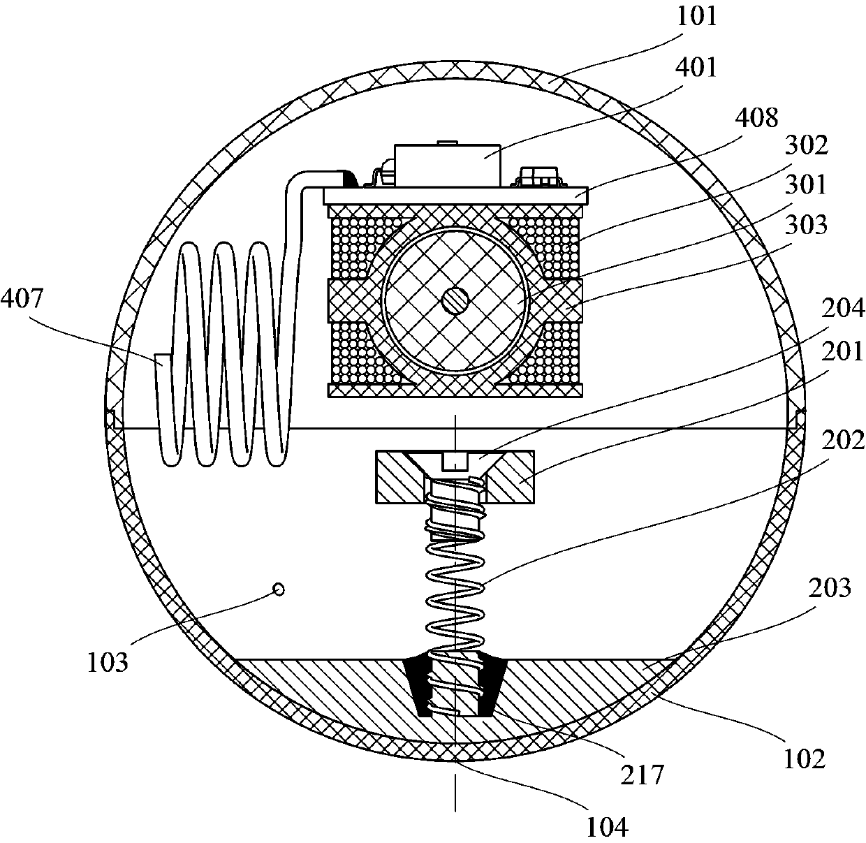
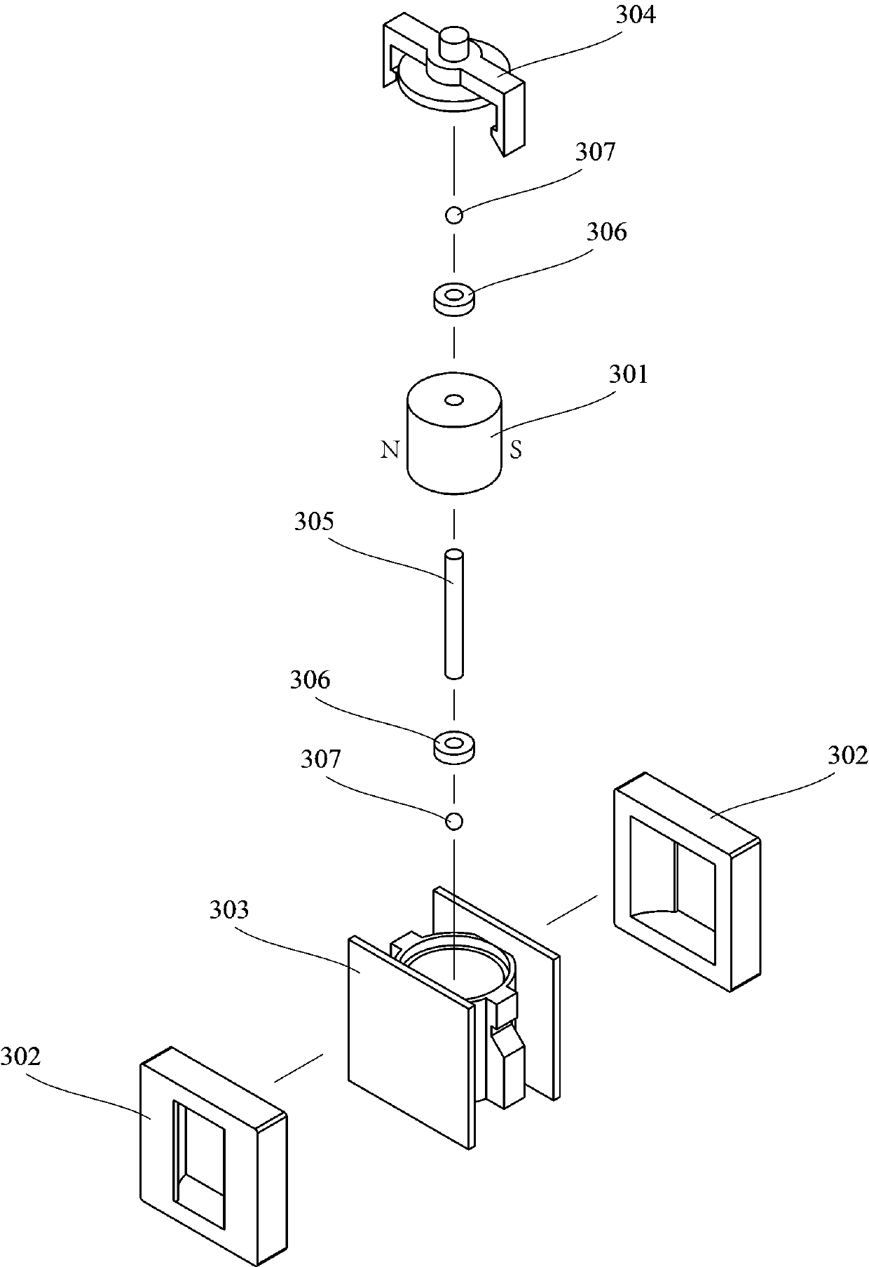
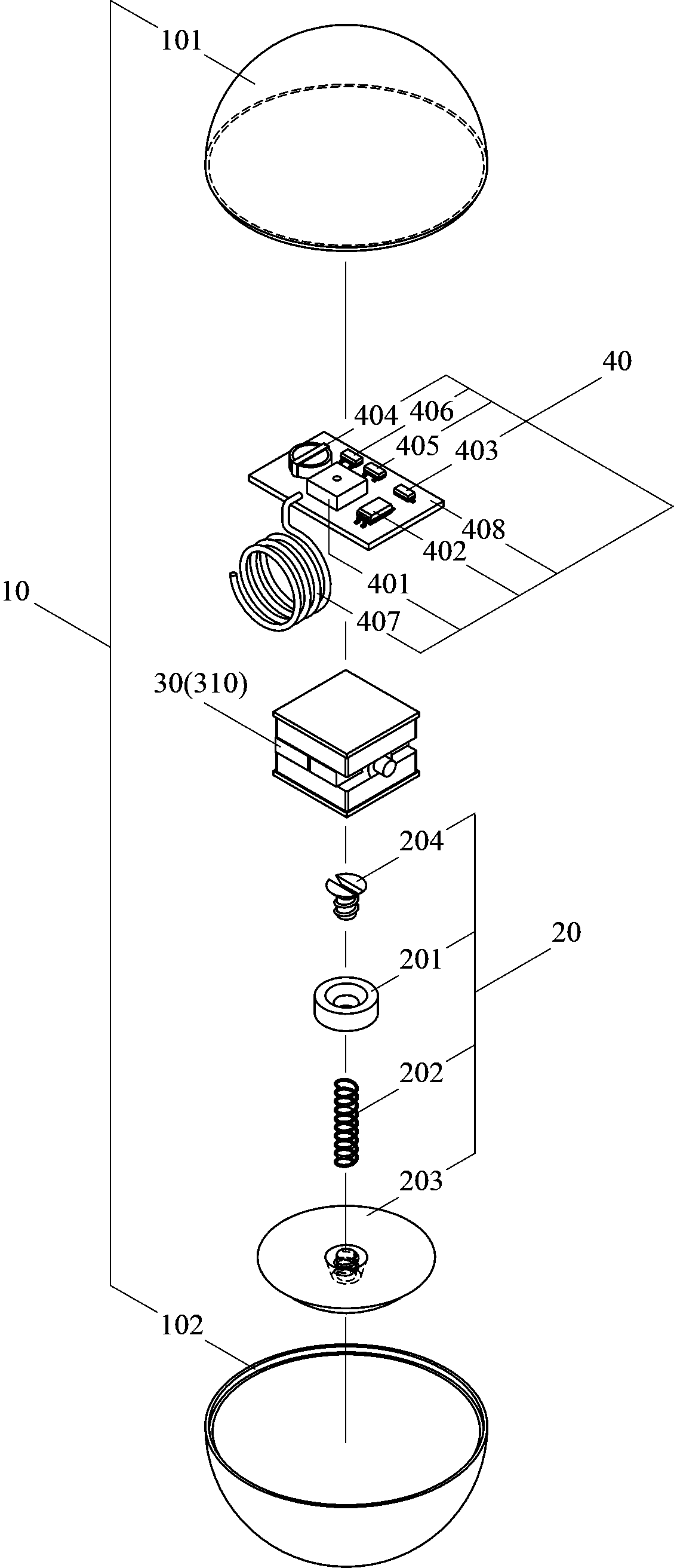
[0039] figure 1 It is a schematic cross-sectional view of this example, showing the internal structure level and connection relationship of this embodiment. refer to figure 1 , the shell 10 is formed by combining the hollow hemisphere A (101) and the hollow hemisphere B (102) through fasteners and gluing or heat-melting (assembly stage), it is noted that there is a vent hole 103 on the shell for balancing the internal and external air pressure; Inside the casing 10, from top to bottom, there are circuit boards 40 ( figure 1Only the tire pressure monitoring chip 401 and the antenna 407 welded on the PCB printed board 408 are shown in the figure. For detailed composition, please refer to image 3 ), power generating device 30 (here is an electromagnetic induction generator 310, its main components are a radially magnetized cylindrical magnetic rotor 301, an induction coil 302, and a skeleton 303, for a preferred structural detail, please refer to figure 2 ), kinetic energy h...

Embodiment 2

[0061] This embodiment has the same parts as Embodiment 1, and to avoid repetition, the same parts will not be described in detail.

[0062] Figure 5 It is a schematic cross-sectional view of this example, showing the internal structure level and connection relationship of this embodiment. refer to Figure 5 , the kinetic energy collection device of this embodiment is different from Embodiment 1, and its working principle is: when shaking kinetic energy or ground impact kinetic energy exist, utilize the pendulum that there is inertia in motion to exist motion state (position, velocity, direction) with current sphere ) difference to collect kinetic energy as the pendulum inertia energy, which will be released to the generator shaft in the form of torque. The difference is manifested as the relative rotation of the pendulum to the housing, which is amplified by the gear set and drives the generator shaft to generate electricity. The kinetic energy harvesting device 20 includ...

Embodiment 3

[0067] Likewise, the parts of this embodiment that are the same as those of Embodiment 1 will not be described again.

[0068] Figure 7 It is a schematic cross-sectional view of this example, showing the internal structure level and connection relationship of this embodiment. refer to Figure 7 , the kinetic energy harvesting device of this embodiment is different from the aforementioned embodiments. The working principle is: when there is ground impact kinetic energy, the weight of the magnet is used to compress the spring to obtain the kinetic energy as the spring compression energy, and then the magnet is bounced up by releasing the elastic force of the spring. , the linear motion of the magnet will cause the coil to cut the magnetic field lines to generate electricity. Kinetic energy acquisition device 20 comprises counterweight 213, nylon cylinder 214, spring 215, silica gel buffer pad 216 among the present example; Described power generation device comprises axial mag...


PUM


Abstract

The invention belongs to the field of automobile spare parts, and discloses a battery-free automobile tire pressure monitoring transmitter capable of freely moving in a tire. The battery-free automobile tire pressure monitoring transmitter comprises a shell, a kinetic energy collecting device, an electric generation device and a circuit board; the shell is composed of two hollow hemispheres, and an air vent is formed in the outer wall; the kinetic energy collecting device is used for collecting rolling kinetic energy, jolting and vibration kinetic energy, shaking kinetic energy or ground touching impact kinetic energy coming from the inner wall of the tire; the electric generation device converts the kinetic energy to alternating current electric energy in an electromagnetic induction electric generation mode; the circuit board comprises a tire pressure monitoring chip and an antenna, and further comprises an energy storage element, a rectifier charging device, a linear voltage regulator and an electric energy detector. Through four links of kinetic energy collecting, kinetic energy releasing, electric generation and charging and electricity supplying, the technical problems in multiple aspects of electricity supplying for the tire pressure monitoring chip are solved, and a plurality of optimized specific implementation plans are provided according to different kinetic energy collecting modes; and according to the battery-free automobile tire pressure monitoring transmitter capable of freely moving in the tire, the structure is simple, reliability is high, using is simple,the cost is low, and market competitiveness is high.

Description

technical field [0001] The invention belongs to the field of auto parts, and relates to a battery-free automobile tire pressure monitoring transmitter capable of free movement in tires. Background technique [0002] Existing automotive tire pressure monitoring transmitters usually have two types, built-in and external, and are generally installed on the tire valve. The tire pressure data is transmitted to the matching display control device or the car center console through narrow-band wireless transmission. Usually, a button battery (such as CR2450) is used for power supply. Due to the limited capacity of the button battery, users need to replace the expensive high-temperature resistant battery regularly. Judging from the current situation, the battery replacement cycle of mid-range priced built-in products is about 2 to 3 years, and it is very inconvenient to change the tires and do dynamic balancing. Some products integrate a high-capacity battery on the sensor, which ca...

Claims


Application Information

Patent Timeline
Patent Type & Authority Applications(China)
IPC IPC(8): B60C23/04H02K7/18H02J7/32
CPCB60C23/04H02J7/32H02J7/345H02K7/1846H02K7/1876
Inventor 向英特
Owner 向英特
Why Eureka
Try Eureka