Prism type light beam scanning device and system for laser micro hole machining and light beam scanning method

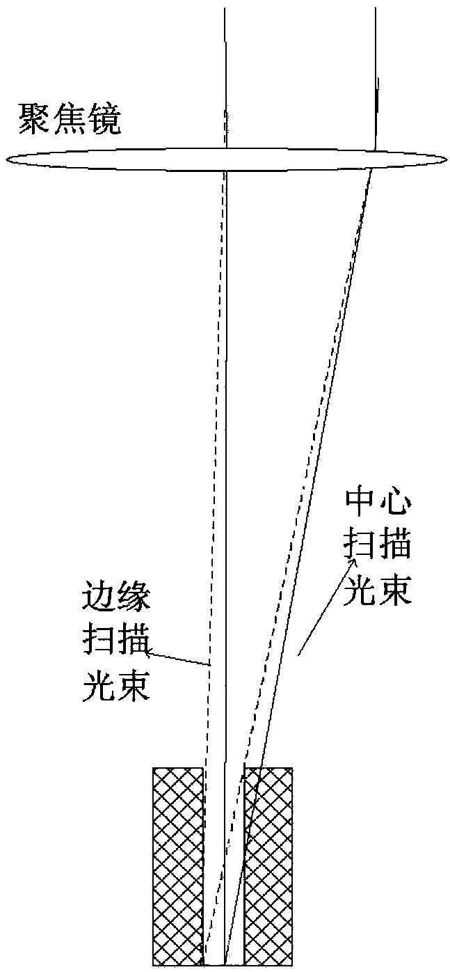
A beam scanning and micro-hole processing technology, used in laser welding equipment, metal processing equipment, manufacturing tools, etc., can solve the problem of rubbing the edge of the center beam first, so as to improve the deep hole processing ability and solve the effect of rubbing the edge first.

Pending Publication Date: 2018-05-25
XIAN MICROMACH TECH CO LTD
View PDF0 Cites 17 Cited by
  • Summary
  • Abstract
  • Description
  • Claims
  • Application Information

AI Technical Summary

Problems solved by technology

[0004] The embodiment of the present invention provides a prism-type beam scanning device, system and beam scanning method for laser microhole processing, so as to at least solve the phenomenon that the center beam first rubs the edge existing in the deep hole processing of the existing transmission type and combined type devices technical issues

Method used


Image

  • Prism type light beam scanning device and system for laser micro hole machining and light beam scanning method
  • Prism type light beam scanning device and system for laser micro hole machining and light beam scanning method
  • Prism type light beam scanning device and system for laser micro hole machining and light beam scanning method

Examples


Embodiment 1

[0061] According to an embodiment of the present invention, a prism-type beam scanning device for laser microhole processing is provided. The beam scanning device is connected to an external control system. The beam scanning device includes: a first special-shaped optical wedge, a second special-shaped optical wedge , the first rotary drive member, the second rotary drive member;

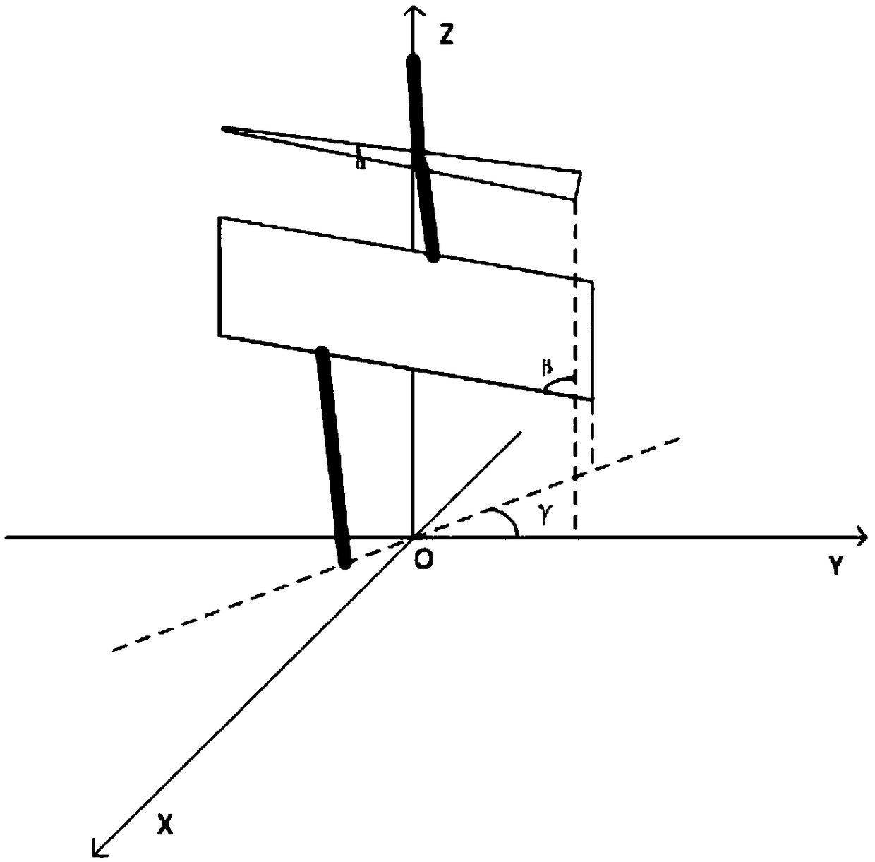
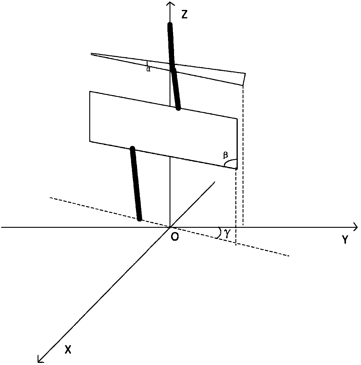
[0062] The first profiled optical wedge includes a first optical wedge portion with an angle α and a first parallel plate portion with an inclination angle β. For the convenience of description, the optical path is described by separating the two parts, which are equivalent to a first optical wedge part with an angle α and a first parallel plate part with an inclination angle β. The surface of the first optical wedge part opposite to the first parallel plate part is the incident surface of the laser light. The laser beam enters the first special-shaped optical wedge from the incident surface and is ...

Embodiment 2

[0068] According to an embodiment of the present invention, a prism beam scanning system for laser microhole machining is provided, including: a laser, a beam expander, a mirror, a two-dimensional beam scanning device, a focusing mirror, a workpiece, and a computer. The computer controls the outgoing beam of the laser. After being collimated by the beam expander, it is reflected by the mirror with a certain installation angle to the two-dimensional beam scanning device to generate an outgoing beam with a certain refraction angle and lateral displacement. Finally, the laser is focused on the workpiece through the focusing mirror. superior. The central line of the light beam reflected by the mirror coincides with the optical axis of the focusing mirror, and the rotation axes of the two special-shaped light wedges in the two-dimensional light beam scanning device are parallel.

[0069] The two-dimensional light beam scanning device is mainly composed of the first special-shaped o...

Embodiment 3

[0082] According to an embodiment of the present invention, a beam scanning method using the above-mentioned beam scanning system is provided. Before using the two-dimensional beam scanning device, the relative positional relationship between two special-shaped optical wedges is first calibrated, and the rotation amount of the driving motor and the The relationship of the initial position for precise control. Build a platform such as Figure 8 As shown: First, a laser beam is emitted from the laser. The laser energy should not be too large, so as not to damage the CCD camera. It is reflected into the beam scanning device by the mirror, and the angle of the mirror is adjusted so that the center line of the beam is in line with the rotation axis of the beam scanning device. Try to coincide; the beam emitted from the beam scanning device is focused by the focusing mirror and then imaged into the CCD camera, where the CCD camera is located at the focal plane of the focusing mirror...


PUM


Abstract

The invention relates to a prism type light beam scanning device and system for laser micro hole machining and a light beam scanning method. The light beam scanning device comprises a first special-shaped optical wedge, a second special-shaped optical wedge, a first rotation driving piece and a second rotation driving piece. The two special-shaped optical wedges are adopted in the light beam scanning device for controlling the transverse displacement and the inclination angle of a laser beam, accordingly, the included angle between the two special-shaped optical wedges is changed, and the inclination angle and the transverse displacement of the laser beam can be changed at the same time. The prism type light beam scanning device can be used for machining an inverted cone hole, meanwhile, the phenomenon that in existing transmission type and combined device deep hole machining, the edge of a center beam is wiped firstly is avoided, and the deep hole machining capability is greatly improved. The light beam scanning system with the above light beams scanning device and the light beam scanning method of the light beam scanning system similarly has the above technical effects.

Description

technical field [0001] The invention relates to the field of laser processing, in particular to a prism-type beam scanning device, system and beam scanning method for laser microhole processing. Background technique [0002] At present, the micro hole processing methods mainly include mechanical drill, electro-hydraulic beam, electric spark, laser and so on. Compared with other processing methods, laser processing has the characteristics of high processing efficiency, wide range of processable materials, no tool wear, non-contact, small influence on material surface, easy orientation, and flexibility. Especially with the application of picosecond and femtosecond lasers, the quality of laser processing has been further improved. Not only the processing accuracy is high, the inner wall quality is good, but also there is no thermal influence, no recast layer, no micro cracks, and no material selectivity. Laser processing has become More and more people choose. [0003] There ...

Claims


Application Information

Patent Timeline
Patent Type & Authority Applications(China)
IPC IPC(8): B23K26/082B23K26/36
CPCB23K26/082B23K26/36
Inventor 李朋杨小君贺斌王宁
Owner XIAN MICROMACH TECH CO LTD
Why Eureka
Try Eureka