
Micro-channel pipeline heat exchanger

A micro-channel heat exchanger and micro-channel technology, applied in indirect heat exchangers, heat exchanger types, lighting and heating equipment, etc., can solve the problems of high cost, complex manufacturing process, easy cracking and leakage, etc. The effect of water flow convection heat transfer area, increasing convection heat transfer area, and enhancing flexural strength

Pending Publication Date: 2018-06-01
GUANGDONG NEW ENERGY TECH DEV
View PDF12 Cites 1 Cited by
  • Summary
  • Abstract
  • Description
  • Claims
  • Application Information

AI Technical Summary

Problems solved by technology

In the casing heat exchanger, the high-temperature refrigerant gas will gradually reduce the temperature in the casing until the gas condenses; the temperature of the circulating water will gradually increase and reach the highest at the outlet, thus realizing the effect of refrigerant condensation and circulating water heating. In order to obtain a larger heat exchange area, the inner tube needs to be bound into a spiral tube through special equipment, and then inserted into the outer tube. At the end of the tube, the inner and outer tubes need to be welded and sealed. The production process of the heat exchanger is complicated, the requirements for the material of the pipe are high, the cost is high, and the weld is easy to crack and leak. The spiral pipe is very thin, and it is easy to corrode and cause leakage during use.

Method used


Image

  • Micro-channel pipeline heat exchanger
  • Micro-channel pipeline heat exchanger

Examples


Embodiment Construction

[0016] The present invention is further described in conjunction with the following examples.

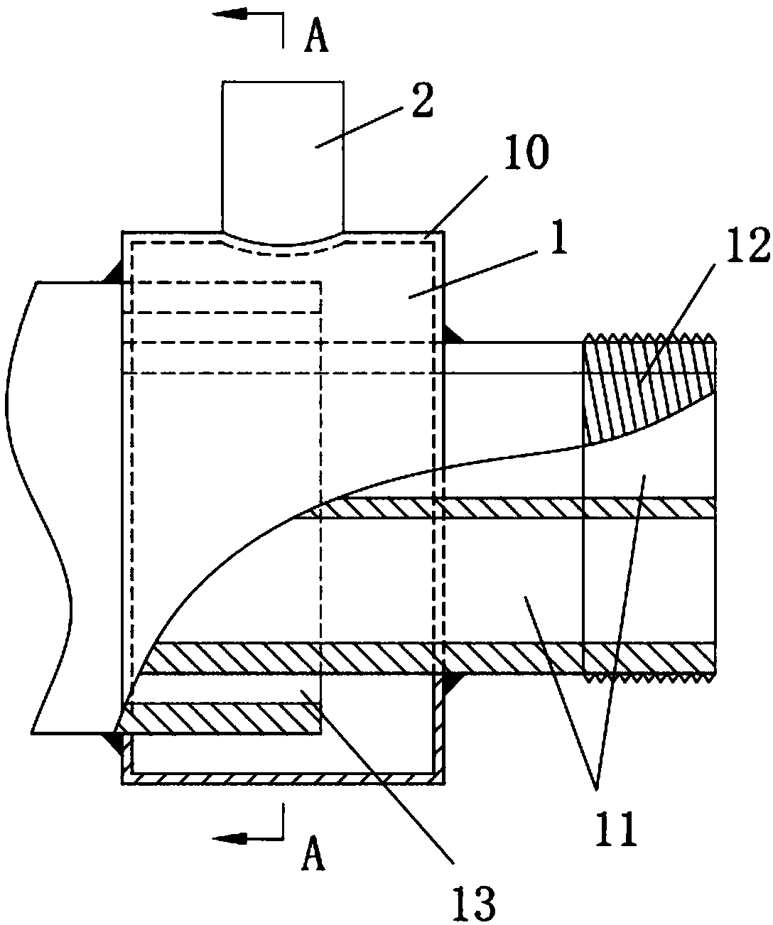
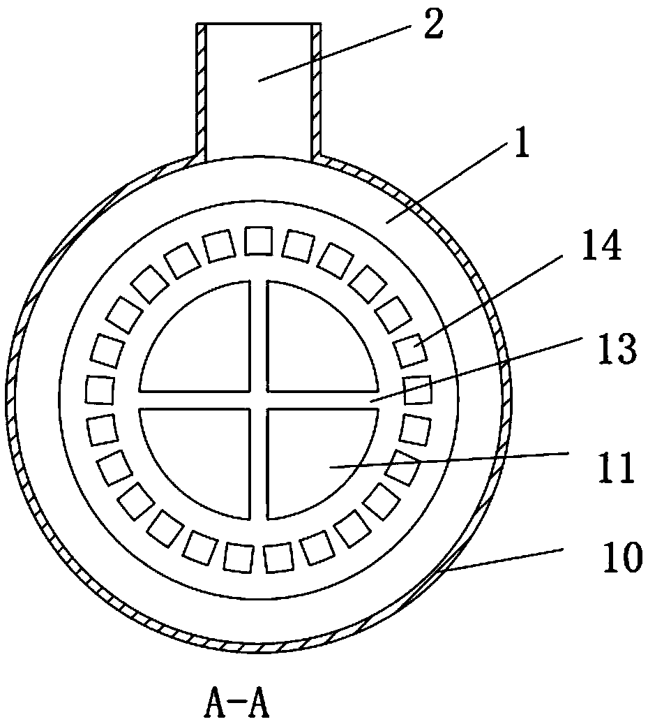
[0017] The specific embodiment of a kind of microchannel 14 pipeline heat exchangers of the present invention, as Figure 1-Figure 2 As shown, the microchannel 14 pipe heat exchanger includes a heat exchanger pipe 1 and an end joint 2 of the heat exchanger pipe 1, and the heat exchanger pipe 1 includes an outer wall 10 and an inner pipe 11, so The inner pipe 11 is a water flow channel, and the inner pipe 11 is extended with a water pipe connector 12. The outer surface of the water pipe connector 12 is provided with an external thread, and the external thread is a mechanically processed connecting thread. 12 is threadedly connected with the external circulating water pipe joint to prevent leakage. The water path flows into the inner pipe 11 through the external circulating water pipe joint. The inner pipe 11 is provided with a connecting rib 13 in the radial direction, and the connec...


PUM


Abstract

The invention provides a micro-channel pipeline heat exchanger. The micro-channel pipeline heat exchanger comprises a heat exchanger pipeline and an end connector of the heat exchanger pipeline; the heat exchanger pipeline comprises an outer wall and an inner pipe; the inner pipe is a water flow channel; a plurality of micro-channels used to enable refrigerants to pass are arranged between the outer wall and the inner pipe; the micro-channels extend along the inner pipe in the axial direction; the micro-channels are orderly arranged around the outer side of the inner pipe and each two adjacentmicro-channels are not connected with each other; the sections of the micro-channels are squares, circles, ovals or polygons; connecting ribs are arranged at the inner pipe in the radius direction and the inner pipe is divided into a plurality of pipelines by the connecting ribs; at least two connecting ribs are arranged and the two connecting ribs are arranged in a staggered manner; one end of the end connector is connected with the micro-channels and the other end of the end connector is connected with a refrigerant pipeline of a refrigeration circulation system; a plurality of connecting ribs are designed at the inner pipe, so that the convection heat exchanging area of water can be greatly increased by the connecting ribs and the heat exchanging efficiency can be high; meanwhile, thebending-resistant strength of the pipeline can be strengthened and the pipeline is not prone to flatten during bending.

Description

technical field [0001] The invention relates to the technical field of heat exchangers for refrigeration, in particular to a microchannel pipe heat exchanger with independent power supply. Background technique [0002] In the existing heat pump water heater units, most of the condensers use sleeve-type heat exchangers, and the sleeve-type heat exchangers are mainly composed of two pipes; The refrigerant flows in the interlayer between the internal threaded tube and the external steel pipe or copper tube. The outer surface of the spiral tube contacts the refrigerant, and the inner surface contacts the circulating water. The refrigerant and water exchange heat with the surface of the spiral tube. The outer and inner walls of the spiral tube pass through The threaded tube metal conducts heat. The outer pipe and the inner threaded pipe are generally connected by welding. Various waterways and refrigerant joints can be designed at the end of the casing. In the casing heat exch...

Claims


Application Information

Patent Timeline
Patent Type & Authority Applications(China)
IPC IPC(8): F25B39/04F28D7/00F28F21/06
CPCF25B39/04F28D7/0008F28F21/062F25B2339/047
Inventor 赵密升李建国杨祖发
Owner GUANGDONG NEW ENERGY TECH DEV
Learn More