A vortex generator-based lateral secondary flow control method for the end wall

A technology of vortex generators and control methods, applied in geometric CAD, design optimization/simulation, special data processing applications, etc., can solve problems such as insufficient estimation of application potential, cumbersome design work, and deterioration of aerodynamic performance, etc., and reach a wide range of applicable fields , increase kinetic energy, and suppress the effect of corner separation

Active Publication Date: 2021-05-25
BEIJING INSTITUTE OF TECHNOLOGYGY
View PDF8 Cites 0 Cited by
  • Summary
  • Abstract
  • Description
  • Claims
  • Application Information

AI Technical Summary

Problems solved by technology

Analyzing this reason, in addition to insufficient estimation of the application potential of vortex generators arranged in blade channels, the main reason is that when vortex generators are applied in blade channels, the design work is too cumbersome and requires repeated geometric modeling and grid generation To determine the optimal solution, some unreasonable designs may even deteriorate the aerodynamic performance

Method used


Image

  • A vortex generator-based lateral secondary flow control method for the end wall
  • A vortex generator-based lateral secondary flow control method for the end wall
  • A vortex generator-based lateral secondary flow control method for the end wall

Examples


Embodiment 1

[0065] This embodiment describes the design and application of a single vortex generator based on a vortex generator-based end wall lateral secondary flow control method of the present invention.

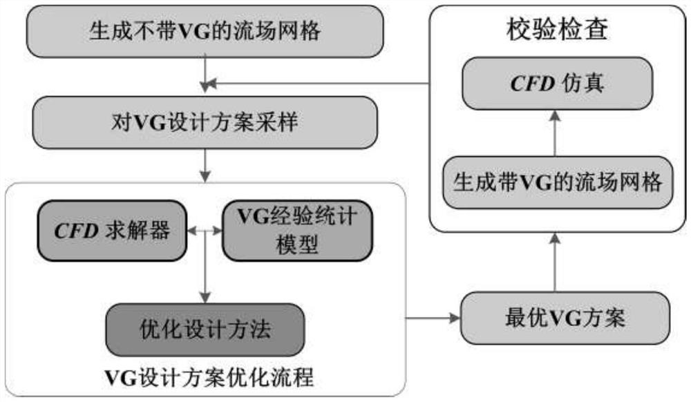
[0066] figure 1 It is a vortex generator-based lateral secondary flow control method on the end wall of the present invention and a flow chart of this embodiment.

[0067] figure 1 Include the following:

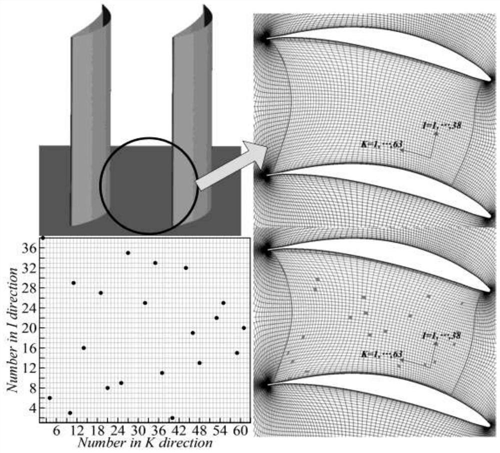
[0068] 1.1 The grid discretization of the position of the end wall, specifically: use the grid of the prototype cascade to remove the grid of the boundary layer encryption part, that is, the following figure 1 Discrete grid of end wall locations shown;

[0069] Based on this, the position of the end wall can be determined along two directions I, K. The value of sequence number I is from 1 to 38, and the value of sequence number K is from 1 to 63. With these two index numbers (I, K) it is possible to define the position of a vortex generator on the end wall. Subsequently, the...

Embodiment 2

[0087] This embodiment describes the design and application of three vortex generators based on a vortex generator-based end wall lateral secondary flow control method of the present invention.

[0088] When designing a single vortex generator, four variables are needed to describe a vortex generator arrangement. Similarly, when designing the arrangement of three vortex generators, 12 parameters are required. Using Latin square sampling to obtain 80 sample points, it took 14 hours to perform serial calculations through the BAYC model. According to the same method as in the previous section, the corresponding response surface is generated with the objective function Obj, and the RMSE value of the response surface is 0.0012. Through the multi-objective genetic algorithm, the optimal scheme under the design and application of three vortex generators is obtained as follows: Figure 7 shown.

[0089] Based on similar settings, the corresponding grids of the optimal scheme of thre...


PUM


Abstract

The invention relates to a method for controlling a lateral secondary flow on an end wall based on a vortex generator, and belongs to the technical field of mechanical devices and transportation. First, the empirical statistical model of the vortex generator is used to simulate its influence on the flow field, thereby avoiding the generation of complex grids describing the vortex generator; secondly, the response surface optimization algorithm is used to conduct a global analysis of the application scheme of the vortex generator in the channel Optimizing; finally, the design results are confirmed by the method of generating real geometric mesh. In the present invention, by applying a vortex generator to the end wall of the blade channel, the high-energy fluid in the mainstream area interacts with the low-energy fluid in the boundary layer, increasing the kinetic energy of the low-energy fluid in the boundary layer, thereby enhancing the ability of the boundary layer to resist pressure gradients and weakening the channel Intensity of the inner lateral secondary flow.

Description

technical field [0001] The invention relates to a method for designing a vortex generator on the end wall of a turbine blade passage, in particular to a method for controlling a lateral secondary flow on the end wall based on the vortex generator, and belongs to the technical field of mechanical devices and transportation. Background technique [0002] The modern design methods of aviation turbines can make the blades work efficiently in the range of 60%-80% mid-span, and the complex flow in the end zone has become the main factor causing aerodynamic blockage, energy loss and performance deterioration [1]. Some studies have shown that the end zone loss accounts for more than 30% of the total loss and worsens with the increase of the turbine aerodynamic load [2]. The corner area of ​​the blade is an inherent geometric feature in the turbine, and the separation of the corner area under the joint action of the boundary layer intersection and the lateral secondary flow is an imp...

Claims


Application Information

Patent Timeline
Patent Type & Authority Patents(China)
IPC IPC(8): G06F30/15G06F30/20
CPCG06F30/15G06F30/20
Inventor 季路成李嘉宾费腾伊卫林
Owner BEIJING INSTITUTE OF TECHNOLOGYGY
Why Eureka
Try Eureka