Resistive inverter robust droop multi-loop control method

A multi-loop control and inverter technology, which is applied in the direction of AC network circuits, electrical components, circuit devices, etc., can solve the problems of large output impedance and unsatisfactory voltage tracking effect, so as to suppress harmonic circulation and improve system transient state Response and current anti-disturbance ability, realize the effect of harmonic current sharing

Inactive Publication Date: 2018-06-05
杨振文
View PDF0 Cites 0 Cited by
  • Summary
  • Abstract
  • Description
  • Claims
  • Application Information

AI Technical Summary

Problems solved by technology

[0004] In order to overcome the problems of unsatisfactory voltage tracking effect and large output i...

Method used


Image

  • Resistive inverter robust droop multi-loop control method
  • Resistive inverter robust droop multi-loop control method
  • Resistive inverter robust droop multi-loop control method

Examples


Embodiment Construction

[0016] specific implementation plan

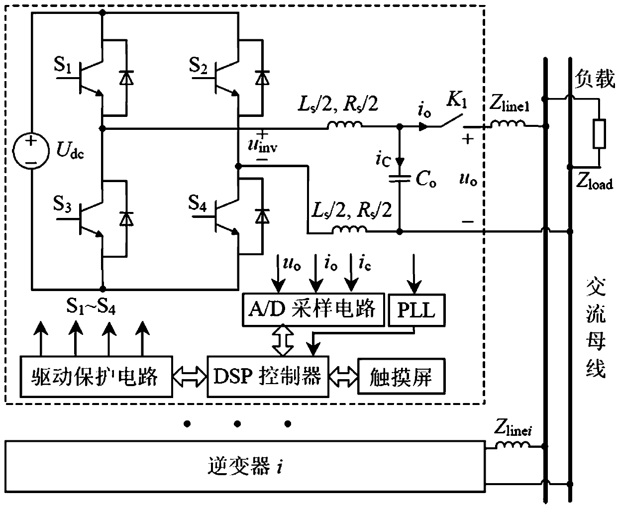
[0017] Such as figure 1 As shown, for a single inverter, it includes a DC source, an inverter circuit, an LC filter circuit, an A / D sampling circuit, a phase locked loop (phase locked loop, PLL), a controller, a drive protection circuit, and the like. DG and energy storage device constitute a relatively stable DC source U dc ; Access switch K 1 and PLL circuit to ensure synchronization with the initial phase of the microgrid voltage when the inverter is connected; Z line is the connection impedance; Z load is the load impedance; L s and R s Respectively, the inductance and line resistance of the filter inductor; C 0 is the filter capacitor; u inv is the no-load output voltage of the inverter; i 0 Output line current for the inverter; u 0 Output voltage for the inverter access point; u L is the load voltage during islanding operation.

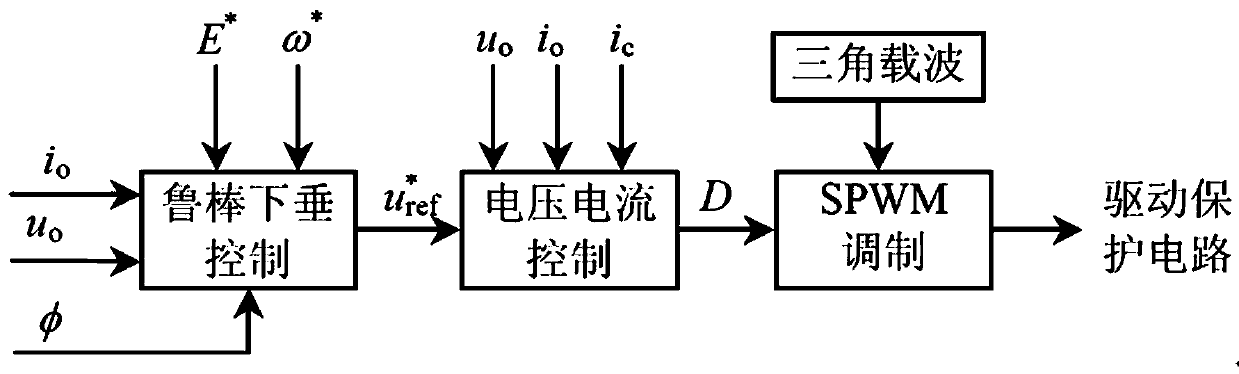
[0018] Such as figure 2 As shown, the control of the parallel inverter mainly includes the r...


PUM


Abstract

The invention discloses a resistive inverter robust droop multi-loop control method, which comprises four parts including application of a multi-inverter parallel system, robust droop multi-loop control, voltage-current double-closed-loop control and SPWM modulation. A power outer loop adopts a robust droop controller, and can reduce the influence of an equivalent output impedance difference on precise distribution of power. The equivalent output impedance of inverters is resistive through introducing virtual complex impedance, the influence of the impedance difference can be reduced, the harmonic circulating current can be suppressed, and harmonic current sharing is realized. By adopting quasi-resonance PR control, zero steady-state error control of output voltages of the inverters in a wider frequency band can be realized, the output voltage deviation between the inverters is reduced, and the circulating current can be suppressed. The resistive inverter robust droop multi-loop control method adopts the voltage-feedforward capacitive current proportional control to improve the transient response and current anti-disturbance capability of the system.

Description

technical field [0001] The invention relates to an inverter control method, in particular to a robust droop multi-loop control method for a resistive inverter. Background technique [0002] Microgrid is an emerging cutting-edge technology based on distributed generation (DG) of new energy (such as wind energy, solar energy, etc.). At present, most of the DG and energy storage devices are connected to the microgrid at the point of common coupling (PCC) through the inverter interface, and then connected to the public grid, thus forming a multi-inverter parallel environment of the microgrid. However, the equivalent output impedance of each inverter is different due to the difference in the control method of the inverter, the nonlinearity of the device, and the filtering parameters; and the distance from the common connection point and the wiring structure also make the line impedance different. Both lead to the increase of the circulating current (fundamental circulating curre...

Claims


Application Information

Patent Timeline
IPC IPC(8): H02J3/38
CPCH02J3/381
Inventor 杨振文
Owner 杨振文
Why Eureka
Try Eureka