

Polyurethane grinding pad and manufacturing method thereof
A polishing pad and polyurethane technology, applied in the polishing field, can solve the problems of difficulty in meeting the integration of integrated circuits, affecting polishing efficiency, scratching the polishing surface, etc., and achieving stable polishing effect, improving polishing efficiency, and reducing scratches.
- Summary
- Abstract
- Description
- Claims
- Application Information
AI Technical Summary
Problems solved by technology
Method used
Image

Examples
Embodiment 1
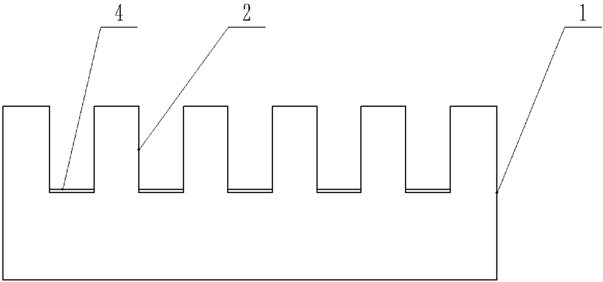
[0043] see figure 1 Shown, a kind of polyurethane polishing pad, comprises the polishing layer 1 obtained by reacting the prepolymer of isocyanate termination, curing agent composition and hollow microsphere, wherein, the amino group in the curing agent composition and unreacted NCO in the prepolymer The molar ratio is 85:100, the average pore size of the polishing layer is 10 μm, and the number of micropores on the surface is 200 / mm 2 , with a roughness of 5 μm. The surface of the polishing layer 1 is provided with a first groove 2 with a concentric circle pattern centered on the center of the polishing layer 1. The cross section of the first groove 2 is rectangular, and the bottom of the first groove 2 has a lubricating coating 4 , wherein, lubricating coating 4 is fluorine-containing polyol, fluorine-containing polyol comprises aliphatic fluorine-containing polyol, aliphatic fluorine-containing polyol contains 6 carbon atoms, and aliphatic fluorine-containing polyol is a mo...
Embodiment 2
[0045] see figure 1 Shown, a kind of polyurethane polishing pad, comprises the polishing layer 1 obtained by reacting the prepolymer of isocyanate termination, curing agent composition and hollow microsphere, wherein, the amino group in the curing agent composition and unreacted NCO in the prepolymer The molar ratio is 95:100, the average pore diameter of the polishing layer is 80 μm, and the number of micropores on the surface is 800 / mm 2 , the roughness is 15 μ m, the surface of the polishing layer 1 is provided with the first groove 2 of the concentric circle pattern with the center of the polishing layer 1 as the center, the cross section of the first groove 2 is rectangular, and the bottom of the first groove 2 has a lubricating coating Layer 4, wherein the lubricating coating 4 is a fluorine-containing polyol, the fluorine-containing polyol includes an aliphatic fluorine-containing polyol, the aliphatic fluorine-containing polyol contains 14 carbon atoms, and the aliphat...
Embodiment 3
[0047] see figure 1 Shown, a kind of polyurethane polishing pad, comprises the polishing layer 1 obtained by reacting the prepolymer of isocyanate termination, curing agent composition and hollow microsphere, wherein, the amino group in the curing agent composition and unreacted NCO in the prepolymer The molar ratio is 90:100, the average pore diameter of the polishing layer is 50 μm, and the number of micropores on the surface is 500 / mm 2 , the roughness is 10 μ m, the surface of the polishing layer 1 is provided with the first groove 2 of the concentric circle pattern with the center of the polishing layer 1 as the center, the cross section of the first groove 2 is rectangular, and the bottom of the first groove 2 has a lubricating coating Layer 4, wherein the lubricating coating 4 is a fluorine-containing polyol, the fluorine-containing polyol includes an aliphatic fluorine-containing polyol, the aliphatic fluorine-containing polyol contains 10 carbon atoms, and the aliphat...
PUM
| Property | Measurement | Unit |
|---|---|---|
| Average pore size | aaaaa | aaaaa |
| Roughness | aaaaa | aaaaa |
| Thickness | aaaaa | aaaaa |
Abstract
Description
Claims
Application Information