
Permanent magnet synchronization traction machine

A synchronous traction machine and permanent magnet technology, applied in the field of traction machines, can solve the problems of complex manufacturing process, far distance between force point and support point, long processing time, etc., and achieve simple and reliable structural design, easy processing and Easy assembly, installation and maintenance

Pending Publication Date: 2018-06-08
WITTUR ELEVATOR COMPONENTS SUZHOU
View PDF0 Cites 1 Cited by
  • Summary
  • Abstract
  • Description
  • Claims
  • Application Information

AI Technical Summary

Problems solved by technology

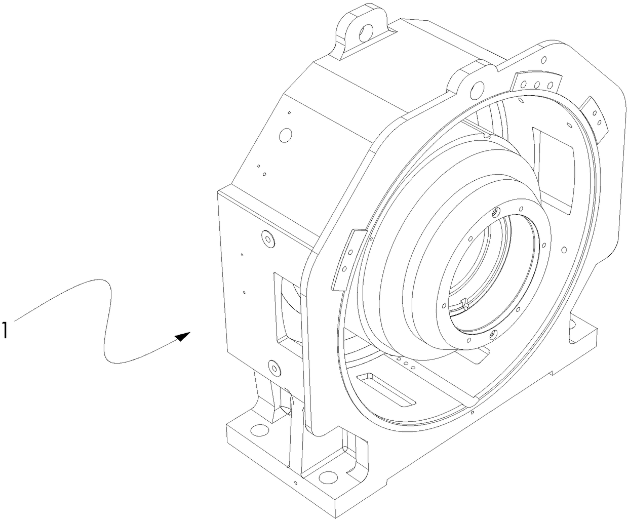
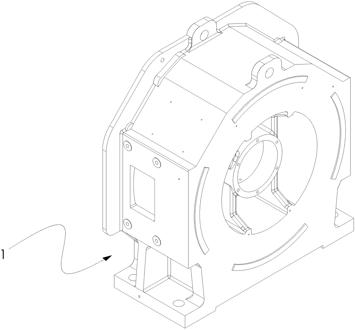
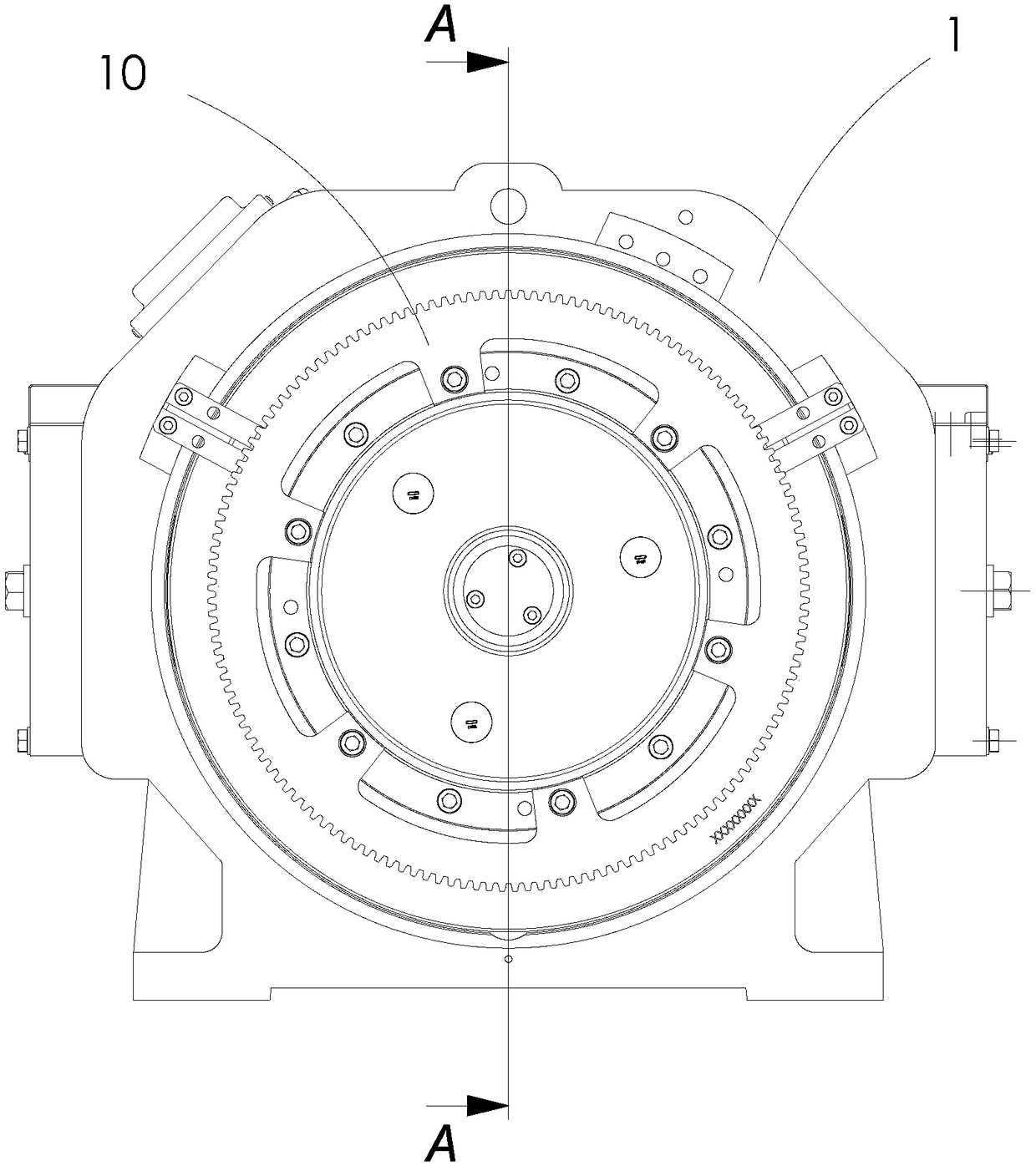
like Figure 1-4 As shown, the machine base in the existing traction machine structure needs to be designed as an internal rotator, and the interior is a larger cavity to install the stator, and the machining and cutting volume is relatively large. After the machining is completed, the concentricity requirements of the front and rear bearings must be ensured. ; and the machining process of the machine base requires the installation of the front and rear bearing holes and stator mounting holes on the machining center, which is costly and complicated, and the processing time is long
[0004] The current design of the traction machine structure has the following disadvantages: after forming, the shape is more complicated and the size factor is not convenient for the measurement of the caliper. For some dimensions, it needs to be completed on the three coordinates; the manufacturing process is complicated and the assembly process is various; the rotor and the frame The structural design is relatively complex, resulting in high cost; the force point and support point in the traction machine frame are far away; the installation method of the encoder in the existing traction machine requires high machining accuracy of the parts, and the encoder disassembly operation space is narrow , there is not enough space for on-site installation; the installation position of the encoder is recessed into the rear cavity of the machine base, and the machine base needs to cast a large enough space cavity

Method used


Image

  • Permanent magnet synchronization traction machine
  • Permanent magnet synchronization traction machine
  • Permanent magnet synchronization traction machine

Examples


Embodiment

[0033] refer to Figure 5-Figure 10 , a permanent magnet synchronous traction machine in this embodiment includes a traction machine base 1, a stator assembly 12, a rotor assembly 11 matched with the stator assembly 12, a traction wheel 10 and a shafting assembly. The structure of the permanent magnet synchronous traction machine in this embodiment is applicable to the welding machine base and the casting machine base, and the welding machine base will be described in detail below.

[0034] The traction machine base 1 in this embodiment is a welded base, including a bottom plate 14 at the bottom, side plates 25 on both sides of the bottom plate 14, and a support plate 15 connecting the side plates 25. The support plate 15 is provided with a Piping 16 of the shafting assembly. The side panels 25 include left and right panels located at both ends of the support panel 15 .

[0035] The side of the pipe 16 and the support plate 15 away from the side plate 25 is also provided wit...


PUM


Abstract

The present invention discloses a permanent magnet synchronization traction machine. The permanent magnet synchronization traction machine comprises a machine base, a stator module, a rotor module cooperated with the stator module, a traction wheel and a shafting module. The machine base comprises a base plate located at the bottom portion, side plates located at two sides of the base plate and asupport plate connected with the side plate, and the support plate is provided with a pipeline; the shafting module comprises a rotating shaft, the rotating shaft is arranged in the pipeline in a penetrating mode, one end of the rotating shaft is connected with the rotor module, and the other end of the rotating shaft is connected with the traction wheel. The permanent magnet synchronization traction machine is reasonable in structure design, and can be suitable for welding and casting of the machine base; the machine based of the permanent magnet synchronization traction machine is simple inshape, has no a periphery and a cavity with complex shapes, and is convenient to measure; a force bearing point is close to a support point in the structure design of the traction machine, and the internal portion shafting and the rotor structure are simple and reliable; and the installation structure of the traction machine coder is reasonable in design, stable in whole frame and low in cost.

Description

technical field [0001] The invention relates to the technical field of traction machines, in particular to a permanent magnet synchronous traction machine. Background technique [0002] With the rapid development of social economy and the continuous improvement of people's living standards, elevators have become an indispensable part of daily life, and the quality requirements for elevator components are getting higher and higher. [0003] At present, the main functions of the machine base are: supporting the front and rear bearings and stator core, installing the brake and supporting the weight of the whole system; the machine base is used to fix the stator and bearings, and it is necessary to ensure the concentricity and runout value of the bearing mounting holes and stator mounting holes. Such as Figure 1-4 As shown, the machine base in the existing traction machine structure needs to be designed as an internal rotator, and the interior is a larger cavity to install the ...

Claims


Application Information

Patent Timeline
Patent Type & Authority Applications(China)
IPC IPC(8): H02K7/10H02K11/21
CPCH02K7/1008H02K11/21
Inventor 焦明旭王友富
Owner WITTUR ELEVATOR COMPONENTS SUZHOU
Learn More