Full energy storage pulse power supply and current pulse generation method

A technology of current pulse and pulse power supply, which is applied in the direction of electric pulse generator circuit, energy storage components to generate pulses, electrical components, etc. It can solve the adverse effects of beam current in the flat top section, the current pulse frequency cannot be too high, and the power supply is difficult, etc. problems, to achieve the effect of improving power quality and power supply reliability, solving high-precision control problems, and realizing cyclic working mode

Pending Publication Date: 2018-06-08
INST OF MODERN PHYSICS CHINESE ACADEMY OF SCI
View PDF5 Cites 3 Cited by
  • Summary
  • Abstract
  • Description
  • Claims
  • Application Information

AI Technical Summary

Problems solved by technology

To sum up, in the traditional pulse power supply with strong excitation voltage, the current pulse frequency cannot be too high, generally within 1 Hz; when the power supply is working, it has a relatively large impact on the power grid, and it is generally necessary to take various measures to compensate for power grid fluctuations and regulation; and the power pulse power is very large, and the required power distribution is also large
[0004] Additionally, if figure 1 As shown in the intermediate voltage waveform, in the current injection section and the flat top section, the current is DC, and the inductor voltage is zero at this time, only the DC voltage, that is, the injection section voltage VP1 and the flat top section voltage VP3 are several times to tens of times lower than the peak voltage VP2 times, it means that the output voltage of the power supply needs to change continuously in a wide range, and the output accuracy of the power supply needs to be guaranteed at each stage, which is very difficult for the power supply
The general situation is to ensure the strong excitation voltage, so that the power supply voltage in the flat top section is very low. For the switching power supply, the duty cycle is very small, which seriously affects the power supply performance.
The DC section is either an injection section or a beam storage stage, which will have an adverse effect on the beam current in the flat-top section.

Method used


Image

  • Full energy storage pulse power supply and current pulse generation method
  • Full energy storage pulse power supply and current pulse generation method
  • Full energy storage pulse power supply and current pulse generation method

Examples


Embodiment Construction

[0034] In order to make the objectives, technical solutions and advantages of the present invention more clearly understood, the present invention will be further described in detail below in conjunction with specific embodiments and with reference to the accompanying drawings.

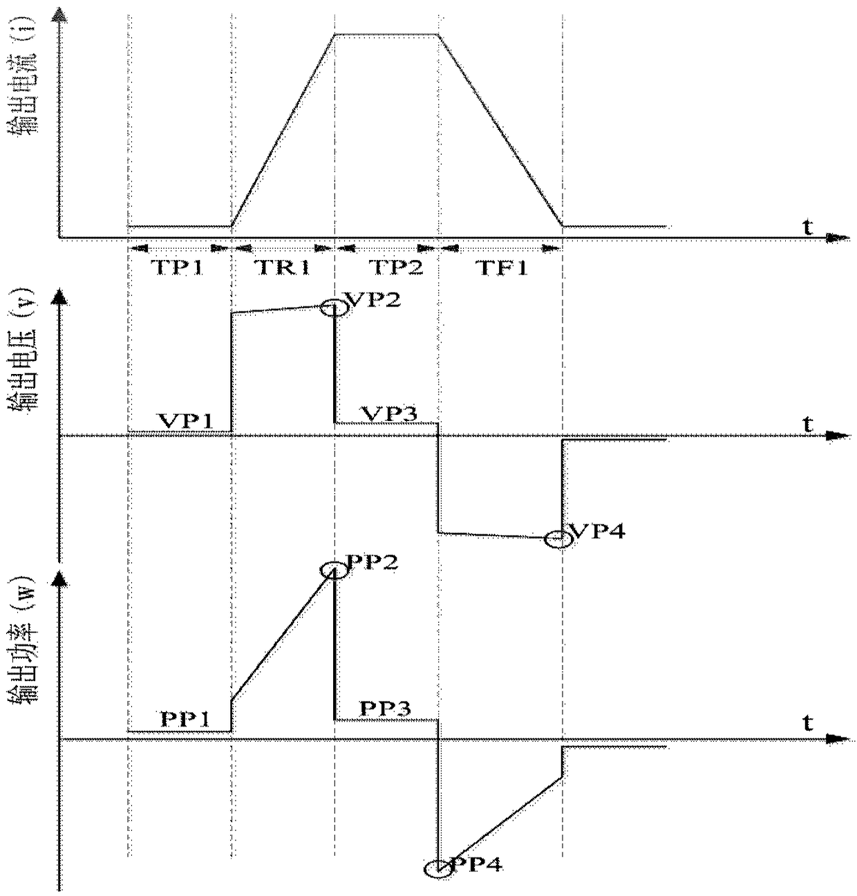
[0035] According to an embodiment of the present invention, a method for generating a current pulse is provided, including: using an energy storage capacitor to store energy, and all the energy required in the rising section of the current waveform pulse is provided by the energy storage capacitor; in the falling section of the current waveform, the magnet load inductance The energy stored in the capacitor is returned to the energy storage capacitor to prepare for the next pulse and realize energy reuse. By charging the high-voltage energy storage capacitor with constant power, the two-way control of energy from the energy storage capacitor to the grid is realized, and the impact on the grid during pow...


PUM


Abstract

The present invention relates to a current pulse generation method. The method comprises the steps of: employing an energy storage capacitor to store energy, wherein energy required by an ascent stageof current waveform pulses is supplied by the energy storage capacitor; and returning energy stored in a magnet load inductor at a descent stage of the current waveform into the energy storage capacitor to be prepared for the next pulse so as to achieve repeat utilization of the energy. The full energy storage mode is employed to specifically solve the main problem of the high excitation power supply of the pulse power supply of a particle accelerator.

Description

technical field [0001] The invention relates to the field of particle accelerators, and also relates to a full energy storage pulse power supply and a current pulse generation method. Background technique [0002] A particle accelerator is a device for accelerating charged particles, in which the particles move in a confined magnetic field, and the magnet and the excitation power supply together constitute the accelerator magnetic field system. Synchrotron is a kind of particle accelerator. When the accelerator accelerates charged particles, the confinement magnetic field needs to be increased synchronously with the increase of the energy of the accelerated particles. Therefore, the excitation current needs to be increased synchronously. When an acceleration cycle is completed, the magnetic field needs to be reduced. To the low position, the accelerated particle beam is injected into the accelerator and is ready to start the next acceleration cycle. The typical working curre...

Claims


Application Information

Patent Timeline
Patent Type & Authority Applications(China)
IPC IPC(8): H02M9/06H03K3/57H05H7/02
CPCH02M11/00H03K3/57H05H7/02H05H2007/022
Inventor 杨建成吴凤军高大庆申国栋燕宏斌夏佳文周忠祖盛丽娜黄玉珍
Owner INST OF MODERN PHYSICS CHINESE ACADEMY OF SCI
Why Eureka
Try Eureka