Quantum coherence effect-based antenna gain measuring device

An antenna gain and quantum coherence technology, applied in the direction of the antenna radiation pattern, etc., can solve the problems of relying on complex measurement devices, unsuitable for industry promotion, and complex measurement procedures, achieving high measurement accuracy, small footprint, and simple procedures.

Active Publication Date: 2018-06-12
NAT INST OF METROLOGY CHINA
View PDF7 Cites 25 Cited by
  • Summary
  • Abstract
  • Description
  • Claims
  • Application Information

AI Technical Summary

Problems solved by technology

This method is currently the most accurate method for gain measurement internationally recognized. However, this method relies on compl

Method used


Image

  • Quantum coherence effect-based antenna gain measuring device
  • Quantum coherence effect-based antenna gain measuring device
  • Quantum coherence effect-based antenna gain measuring device

Examples


Embodiment 1

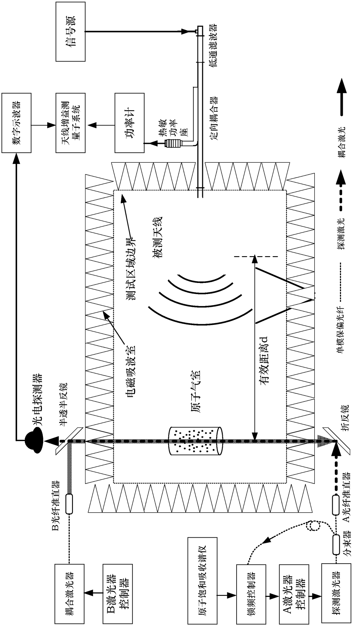
[0071] Embodiment The gain measurement device of the present invention is described by taking the gain measurement of a typical K-band (18GHz-26.5GHz) horn antenna as an example. Select three frequency points (18.404GHz, 21.665GHz and 25.745GHz) in the frequency band for antenna gain measurement.

[0072] The size of the rectangular mouth of the horn antenna used in the embodiment is 38.55mm×29.46mm, and the far-field distance corresponding to 26.5GHz is 413.6mm. In order to take into account the space and far-field conditions of the electromagnetic absorbing chamber of the device of the present invention, the distance from the antenna mouth to the laser beam is determined The distance is 600mm.

[0073] (1) after selecting the antenna to be tested, check each instrument in the device of the present invention:

[0074] 1. Preheat the instrument;

[0075] Both the semiconductor laser and the thermal power meter are sensitive to the temperature of the external environment. For...


PUM


Abstract

The invention discloses a quantum coherence effect-based antenna gain measuring device. The device comprises an electromagnetic wave absorbing chamber, an atomic gas chamber, a laser light source subsystem, a spectral signal measurement subsystem, a power measurement subsystem, an antenna gain measurement subsystem and a plurality of support platforms. According to the device disclosed by the invention, an optical device is used for triggering an energy spectrum, so that atoms are induced. An energy spectrum is obtained through photoelectric detection. Meanwhile, the wave-absorbing material isadopted to prevent an electromagnetic scattering body from affecting the measurement. Through measuring the feed-in net power of a measurement antenna and the net power of the coupling port of a directional coupler, the data acquisition of the transmitted spectrum of the detection light is completed. A power meter is connected with a computer through a GPIB bus, so that the reading of the feed-inpower value of the antenna is completed. Through an antenna gain measurement model (img file = 'DDA 0001510521350000011.T'wi = '355 'he = '170 '), the gain measurement is completed. Compared with a traditional antenna measuring system, the device has the advantages of high measurement precision, low construction cost, small occupied area and the like.

Description

technical field [0001] The invention relates to the technical field of antenna measurement, in particular to a precise measurement method and device for antenna gain based on quantum coherence effect. Background technique [0002] The function of the antenna is to convert the guided waves on the transmission structure into free space waves. Antenna is an important component of communication system as a waveguide system and a converter of free space electromagnetic field. There are many parameters to describe the performance of the antenna, among which the gain describes the ability of the antenna to receive or transmit signals in a certain direction. Antenna gain refers to the ratio of the radiation intensity in a given direction to the radiation intensity obtained when the received power is radiated by an isotropic antenna; when the direction is not specified, it defaults to the direction of the maximum radiation intensity of the antenna. According to actual needs, the an...

Claims


Application Information

Patent Timeline
IPC IPC(8): G01R29/10
CPCG01R29/10
Inventor 宋振飞李大博张万锋刘欣萌
Owner NAT INST OF METROLOGY CHINA
Why Eureka
Try Eureka