10MHz-10GHz optical phase-locked loop device

A phase-locked loop and optical technology, applied in the field of optical phase-locked loops, can solve problems such as unusable, fixed center frequency, lack of universality, etc., and achieve the effect of easy operation

Active Publication Date: 2018-06-22
SHANXI UNIV
View PDF3 Cites 3 Cited by
  • Summary
  • Abstract
  • Description
  • Claims
  • Application Information

AI Technical Summary

Problems solved by technology

However, the same as the acousto-optic modulator, the modulation bandwidth of the electro-optic modulator is only about 100 MHz, and the center frequency of the commerc

Method used


Image

  • 10MHz-10GHz optical phase-locked loop device
  • 10MHz-10GHz optical phase-locked loop device
  • 10MHz-10GHz optical phase-locked loop device

Examples


specific Embodiment approach

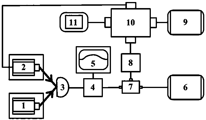
[0017] In this embodiment, the frequency difference between the locked output two beams corresponds to 133 Two lasers for the ground state hyperfine splitting of Cs atoms (9.2 GHz) are taken as an example, as figure 1 As shown, a 10 MHz-10 GHz optical phase-locked loop device, including a titanium sapphire laser 1, a semiconductor laser 2, a high-bandwidth photodetector 3 (KG-PD-20G-A produced by Beijing Kangguan Century Optoelectronics Technology Co., Ltd. -SM-FA), RF power beam splitter 4 (ZX10-2-1252+ produced by Mini-Circuits Company), spectrum analyzer 5, high frequency signal generator 6 (MG3692B-20-GHz produced by Anrits Company), Mixer 7 (ZMX-10G+ produced by Mini-Circuits Company), RF power amplifier 8 (ZHL-1-2W+ produced by Mini-Circuits Company), signal generator 9, optical phase-locked loop module 10 (produced by Toptica Company mFALC110, its input signal bandwidth is 10 MHz-200 MHz, the best input power range of RF port is -35 dBm-1 dBm, the best input power rang...


PUM


Abstract

The invention relates to the field of optical phase-locked loops and provides a 10MHz-10GHz optical phase-locked loop device. The device includes a titanium-doped sapphire laser (1), a semiconductor laser (2), a high-bandwidth photoelectric detector (3), a radio frequency power beam splitter (4), a spectrum analyzer (5), a high-frequency signal generator (6), a frequency mixer (7), a radio frequency power amplifier (8), a signal generator (9), an optical phase-locked loop module (10), and an oscilloscope (11). The device can make the frequency difference between the two lasers fixed in the range of 10MHz to10GHz, and the device can stably and continually work and is less affected by the external environment.

Description

technical field [0001] The present invention relates to the research field of nonlinear optics and quantum optics of coherent media between light and atoms, such as the technical fields of electromagnetically induced transparency, multi-wave mixing, quantum imaging, quantum precision measurement, etc. The field of optical phase-locked loops in nonclassical states of light fields. Background technique [0002] The atomic coherence effect plays an important role in the nonlinear process of light-atom interaction. The coherent medium composed of phase coherent light and atoms has been widely used in the experimental research of quantum optics, such as electromagnetically induced transparency, quantum communication, multi-wave mixing, and laser cooling and trapping atoms. In the above applications, it is necessary to generate two or more beams with frequency difference of several GHz and constant phase difference. For example, the hyperfine splitting of the ground state of rub...

Claims


Application Information

Patent Timeline
IPC IPC(8): G02F1/35H04B10/516H04B10/70H03L7/18
CPCG02F1/3501G02F1/353H03L7/18H04B10/516H04B10/70
Inventor 秦忠忠马荣刘伟苏晓龙贾晓军彭堃墀
Owner SHANXI UNIV
Why Eureka
Try Eureka