Low cost input anti-overvoltage protection circuit
An overvoltage protection circuit, a low-cost technology, applied in the field of circuits, can solve the problems of increased circuit cost and volume, inability to protect subsequent circuits, short overvoltage working time, etc., to achieve adjustable overvoltage protection threshold and EMC performance Superior, simple and reliable circuit effect
- Summary
- Abstract
- Description
- Claims
- Application Information
AI Technical Summary
Problems solved by technology
Method used
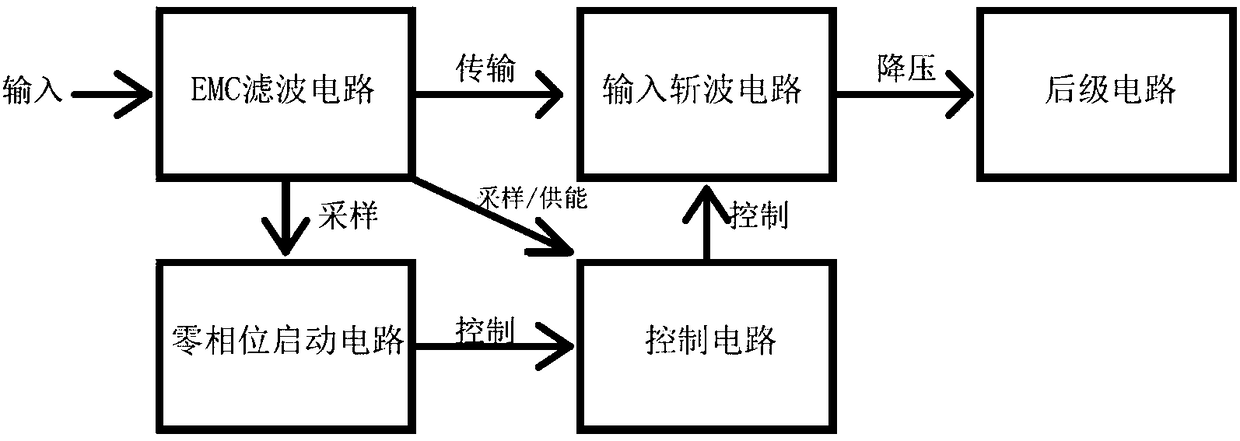
Image

Examples
no. 1 example
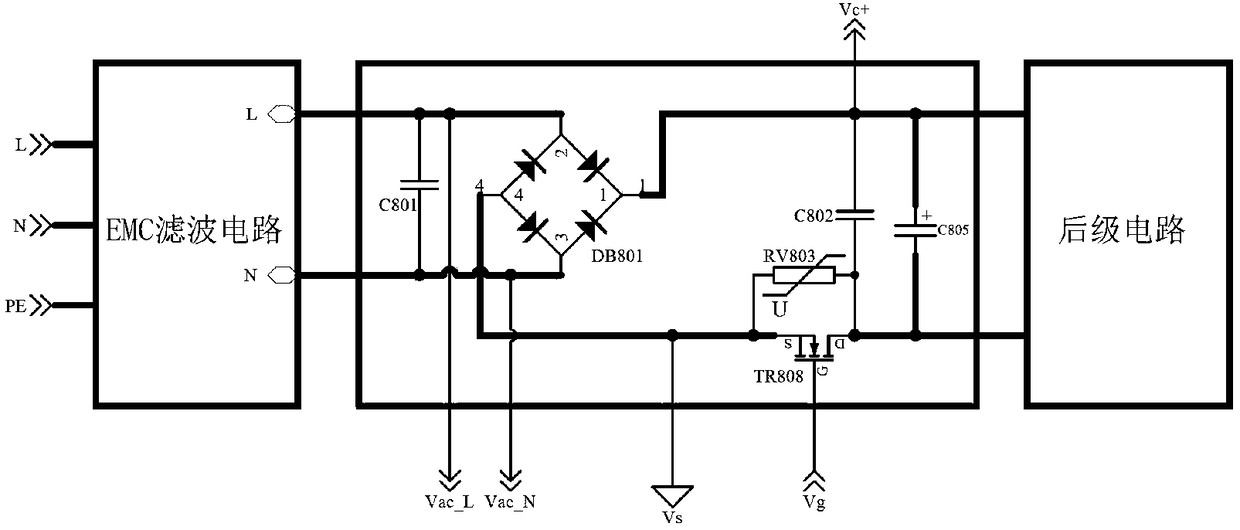
[0044] figure 2 It is the schematic diagram of the input chopper circuit of the first embodiment of the present invention, including: capacitor C801, rectifier bridge DB801, capacitor C802, varistor RV803, N-channel MOS transistor TR808 and energy storage capacitor C805.
[0045] Capacitors C801 and C802 are safety capacitors, and the Vds of N-channel MOS transistor TR808 is recommended to be above 650V.
[0046] Both ends of the safety capacitor C801 are connected to the L and N terminals of the front-end EMC filter circuit, and are respectively connected to the two AC input terminals of the rectifier bridge DB801: the first input terminal and the second input terminal, and the source of the MOS transistor TR808 (S ) is connected to the negative pole of the rectifier bridge DB801, the drain (D) of TR808 is connected to the negative pole of the energy storage capacitor C805, and connected to one end of RV803 and C802, and the other end of the piezoresistor RV803 is connected ...
no. 2 example
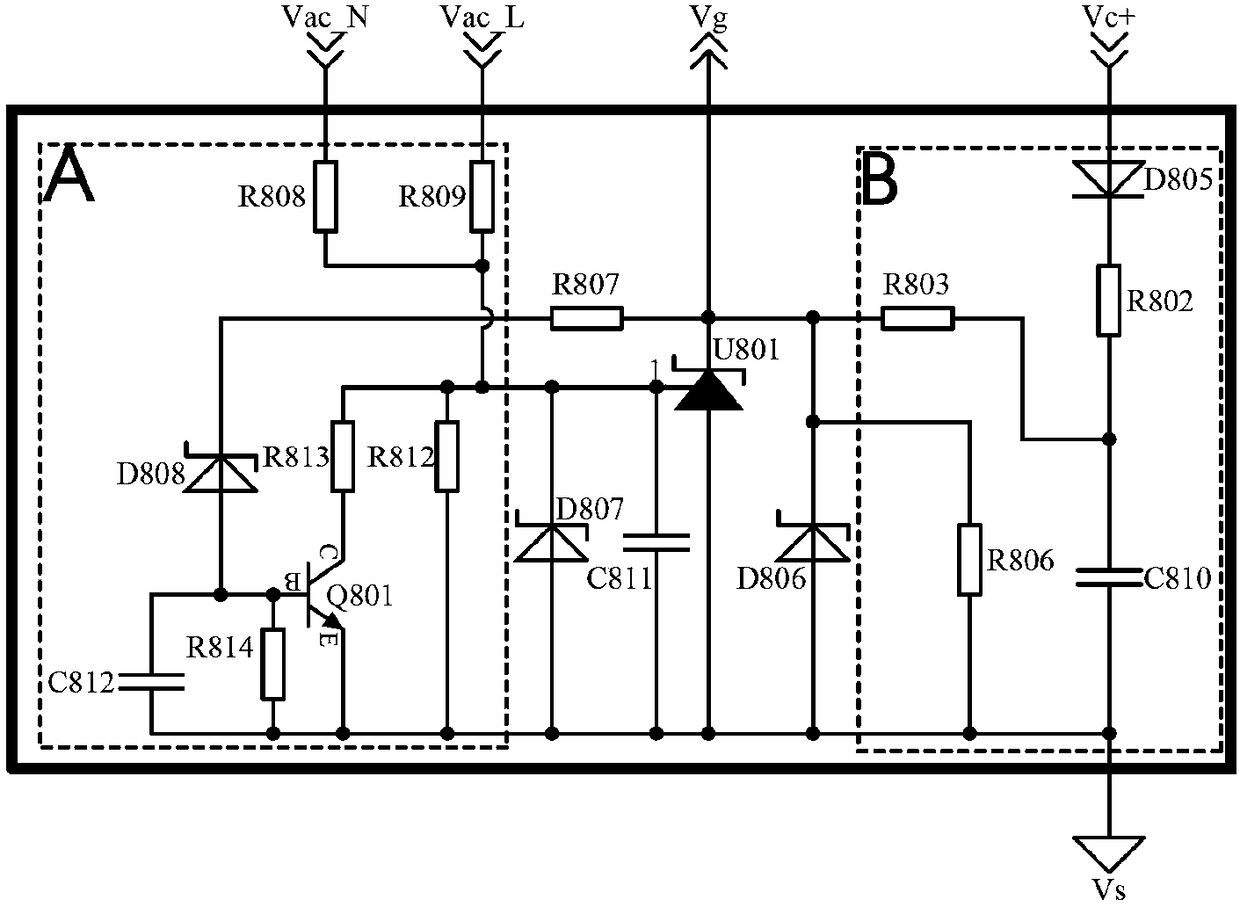
[0059] Figure 4 It is the schematic diagram of the input chopper circuit in the second embodiment of the present invention. The difference from the first embodiment is that the N-channel MOS transistor TR808 is changed to the P-channel MOS transistor TR809, and the connection relationship is adjusted as follows: TR809 The gate of TR809 is connected to the control signal Vg output by the control circuit, the source of TR809 is connected to the positive pole of rectifier bridge DB801, and the drain of TR809 is connected to the positive pole of energy storage capacitor C805. Both ends of RV803 are connected in parallel between source and drain of TR809. The connection relationship of other components remains unchanged. At the same time, the control circuit is properly adjusted and isolated.
[0060] The working principle of the adjusted circuit is the same as that of the first embodiment, and the same effect can be realized.
no. 3 example
[0062] Figure 5 to Figure 8 It is the schematic diagram of the input chopper circuit in the third embodiment of the present invention. The difference from the first embodiment is that the MOS tube TR808 is changed to a relay TR810, and the connection mode of the relay is one of the following four types:
[0063] The first type: the first control terminal of the relay is connected to the control signal Vg output by the control circuit, the second control terminal of the relay is connected to the signal ground of the control circuit, the first switch terminal of the relay is connected to the negative pole of the rectifier bridge DB801, and the second switch of the relay The terminal is connected to the negative pole of the energy storage capacitor C805; the two ends of the RV803 are respectively connected to the first switch terminal and the second switch terminal of the relay.
[0064] The second type: the first control terminal of the relay is connected to the control signal Vg...
PUM
 Abstract
Description
Claims
Application Information