Ultrasound drug assisted treatment device
A technology of adjuvant therapy and drugs, which is applied in the direction of drug devices, other medical devices, and body negative resistance devices to generate pulses. It can solve the problems of ineffective drug penetration and achieve good application prospects, good treatment, and improved penetration effects. Effect
- Summary
- Abstract
- Description
- Claims
- Application Information
AI Technical Summary
Problems solved by technology
Method used
Image

Examples
Embodiment Construction
[0027] The present invention will be further described below in conjunction with the accompanying drawings.
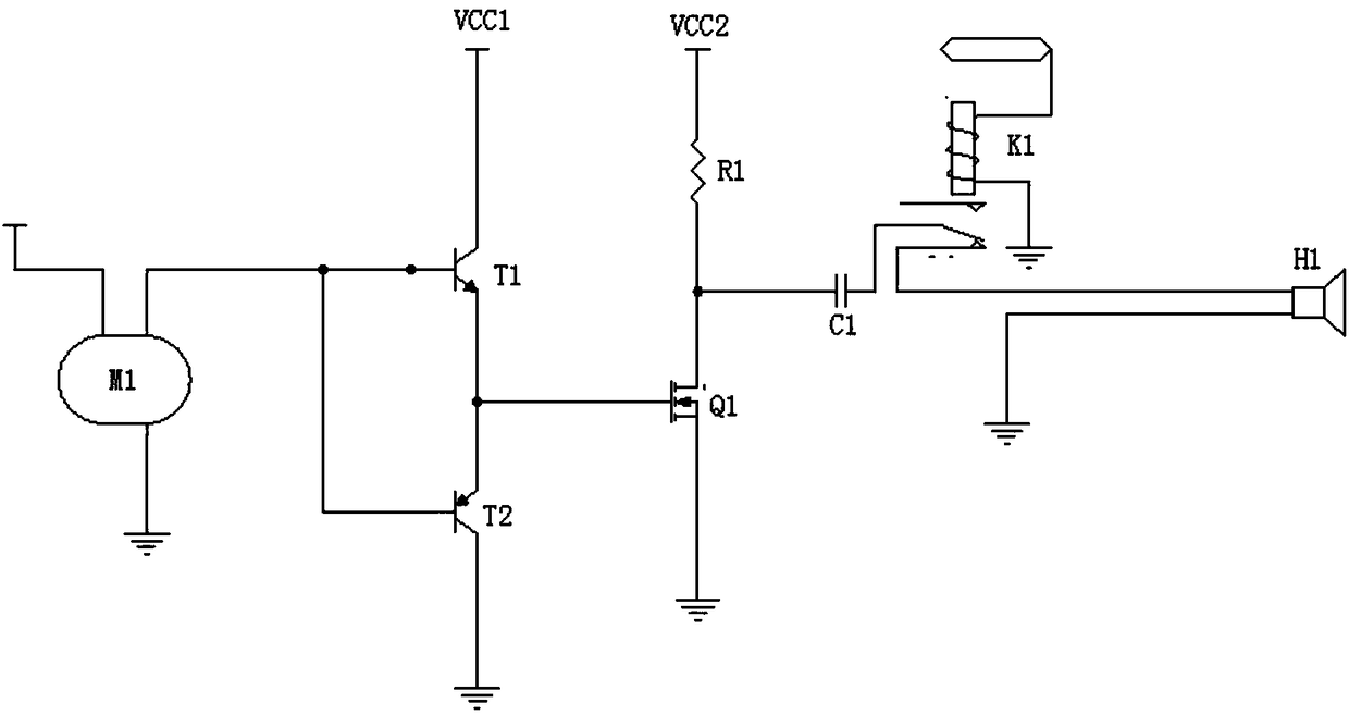
[0028] The ultrasonic drug-assisted treatment device of the present invention includes an integrated ultrasonic excitation pulse generation circuit, an electroporation pulse generation circuit, an electrical stimulation signal generation circuit and a single-chip microcomputer,
[0029] Such as figure 1 As shown, the ultrasonic excitation pulse generating circuit includes an active crystal oscillator M1, a push-pull amplifier circuit, a first gating circuit and an ultrasonic transducer H1, and the active crystal oscillator M1 sequentially passes through the push-pull amplifier circuit, the first selected The pass circuit is connected with the ultrasonic transducer H1, and the first select circuit is connected with the first control signal output end of the single-chip microcomputer for controlling the operation or stopping of the ultrasonic transducer H1,
[0030] The...
PUM
 Abstract
Description
Claims
Application Information
PatSnap Eureka turns technology decisions into work you can execute. Powered by our Innovation Knowledge Graph, it runs expert workflows across engineering, life sciences, materials and intellectual property. Get your review-ready output in minutes.


