
Laser micro-hole machining cooperative control system and method based on industrial personal computer

A technology of collaborative control and micro-hole processing, applied in general control systems, control/regulation systems, program control, etc., can solve the problems of low processing reliability, processing accuracy and processing efficiency difficult to meet processing requirements, etc., to ensure reliability and reliability. High efficiency, friendly human-computer interface, and high workpiece accuracy

Active Publication Date: 2018-06-29
SHENYANG GOLDING NC & INTELLIGENCE TECH CO LTD
View PDF4 Cites 10 Cited by
  • Summary
  • Abstract
  • Description
  • Claims
  • Application Information

AI Technical Summary

Problems solved by technology

[0003] Laser micro CNC machine tools are the product of the combination of laser technology and numerical control technology, but the existing laser CNC machine tools are difficult to meet the processing requirements in terms of processing accuracy and processing efficiency in micro hole processing, and there are also problems of low processing reliability

Method used


Image

  • Laser micro-hole machining cooperative control system and method based on industrial personal computer
  • Laser micro-hole machining cooperative control system and method based on industrial personal computer
  • Laser micro-hole machining cooperative control system and method based on industrial personal computer

Examples


Embodiment Construction

[0035] The present invention will be further described below in conjunction with the accompanying drawings.

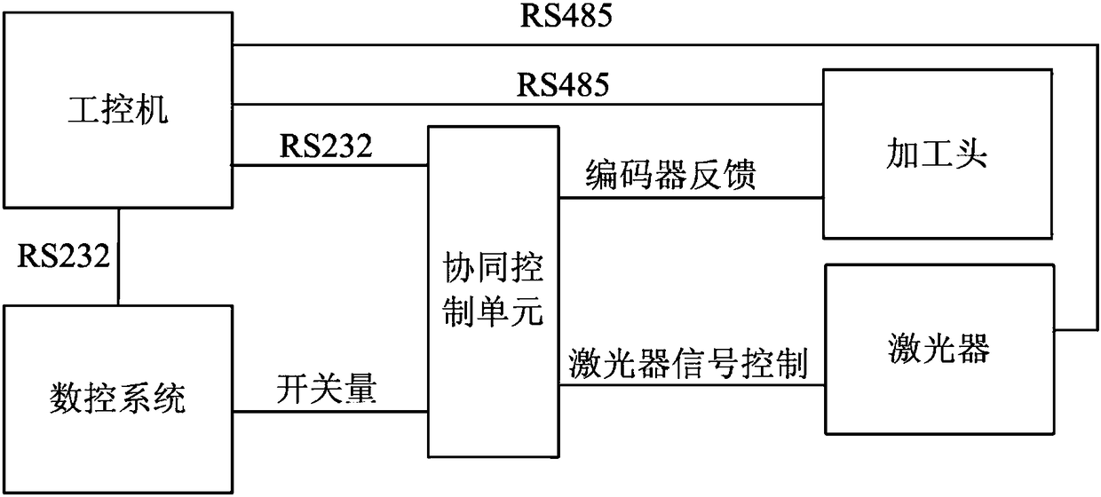
[0036] The structure of the control system of the present invention is as follows: figure 1 As shown, the system control structure is mainly composed of three parts, namely: industrial computer control part, numerical control system part, cooperative control unit part. The specific communication interaction of these three parts is as follows:

[0037] 1) The industrial computer is connected with the cooperative control unit and the numerical control system through the RS232 interface, and receives relevant state parameters from the cooperative control unit and transmits them to the numerical control system; at the same time, it reads the current operating parameters and status information of the processing head; controls the switch of the laser and receives Status information fed back by the laser;

[0038] 2) The industrial computer transmits the hole-making process...


PUM


Abstract

The invention relates to a laser micro-hole machining cooperative control system and method based on an industrial personal computer. The system comprises the industrial personal computer, a numericalcontrol system and a cooperative control unit. The method comprises the steps that the industrial personal computer acquires machining parameters from a technological database according to operationof a user, sends a control command to the numerical control system according to the machining parameters and sends configuration parameters to the cooperative control unit; a laser is controlled to bestarted and stopped, and state information fed back by the laser is received; the numerical control system controls movement of a machine tool spindle according to the control command and controls the cooperative control unit to be started and stopped; and the cooperative control unit receives the configuration parameters, the starting and stopping quantity sent by the numerical control system and position information fed back by an adjusting motor of a machining head and sends a control signal to the laser, and circular constant-overlapping-ratio spiral scanning machining control is achieved. According to the laser micro-hole machining cooperative control system and method based on the industrial personal computer, the cooperative control unit coordinates work of the machining head and the laser and can control the whole machining process in real time, the machining reliability and high efficiency are guaranteed, and meanwhile the precision of a machined workpiece is high.

Description

technical field [0001] The invention belongs to the field of laser microhole processing numerical control machine tools, and in particular relates to an industrial computer-based laser microhole processing cooperative control system and a method thereof. Background technique [0002] Laser processing technology has a series of advantages such as flexible processing methods, fast processing speed, high precision of processed workpieces, and less waste of processed materials. It is widely used in machinery manufacturing, medical equipment, automobiles, aerospace, electronic circuits and other industries. With the development of manufacturing industry and the popularization of computer technology, numerical control technology is more and more widely used in manufacturing industry, and it is an important part of manufacturing informatization. The combination of laser processing technology and numerical control machine technology has become the key technology of modern industrial...

Claims


Application Information

Patent Timeline
Patent Type & Authority Applications(China)
IPC IPC(8): B23K26/384G05B19/414
CPCB23K26/384G05B19/4142
Inventor 王超何忠锴王喆武南李博刘春亮
Owner SHENYANG GOLDING NC & INTELLIGENCE TECH CO LTD
Learn More