Oily sludge treatment machine

A processing machine and sludge technology, applied in the direction of dewatering/drying/concentrating sludge treatment, etc., can solve the problems of huge equipment investment, secondary air pollution, complicated operation, etc., and achieve high drying efficiency, easy operation and small size Effect

Pending Publication Date: 2018-06-29
山东九择环保设备有限公司
View PDF3 Cites 0 Cited by
  • Summary
  • Abstract
  • Description
  • Claims
  • Application Information

AI Technical Summary

Problems solved by technology

[0004] 1. Incineration method: This process causes serious secondary pollution, and the crude oil with high economic value in the sludge has not been recycled; 2. Pyrolysis method: This method has a fast processing speed and a more thorough treatment of sludge. The disadvantage is that the reaction conditions are high, the operation is complicated, the equipment investment is huge, the energy consumption is high, and the secondary pollution of the atmosphere is easy to be generated if the treatment is not good.
The remaining processing technologies are currently limited to laboratory research, and it is difficult to achieve industrial application

Method used


Image

  • Oily sludge treatment machine
  • Oily sludge treatment machine
  • Oily sludge treatment machine

Examples


Embodiment Construction

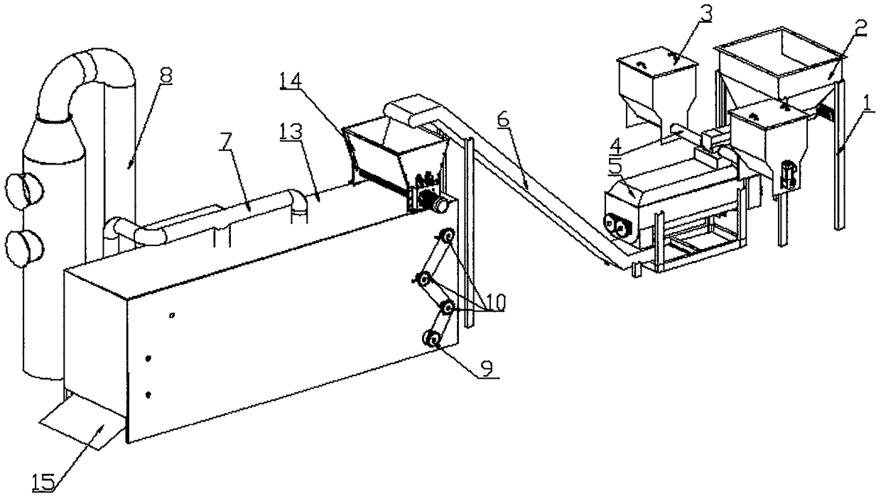
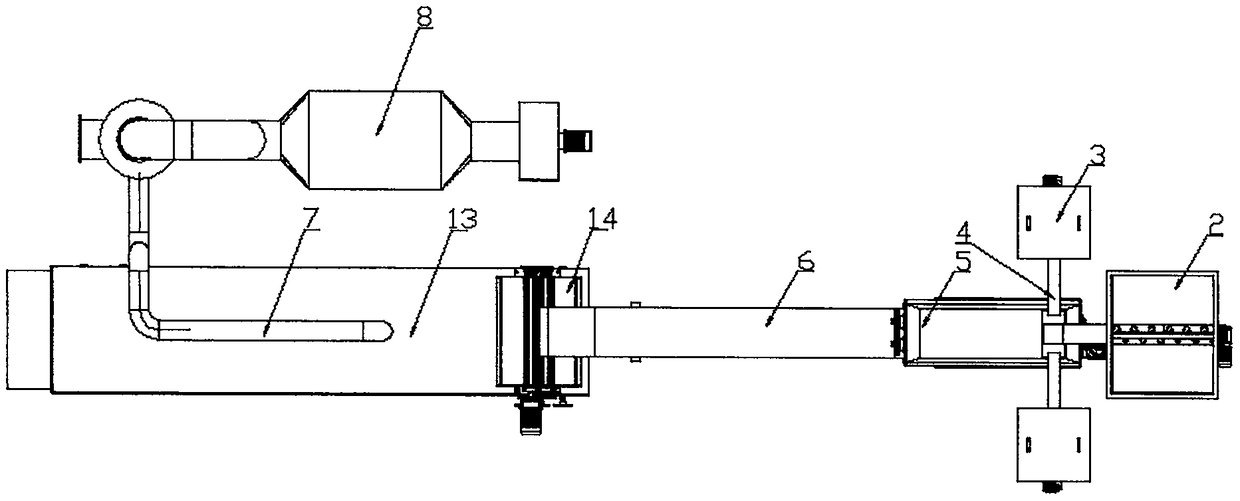
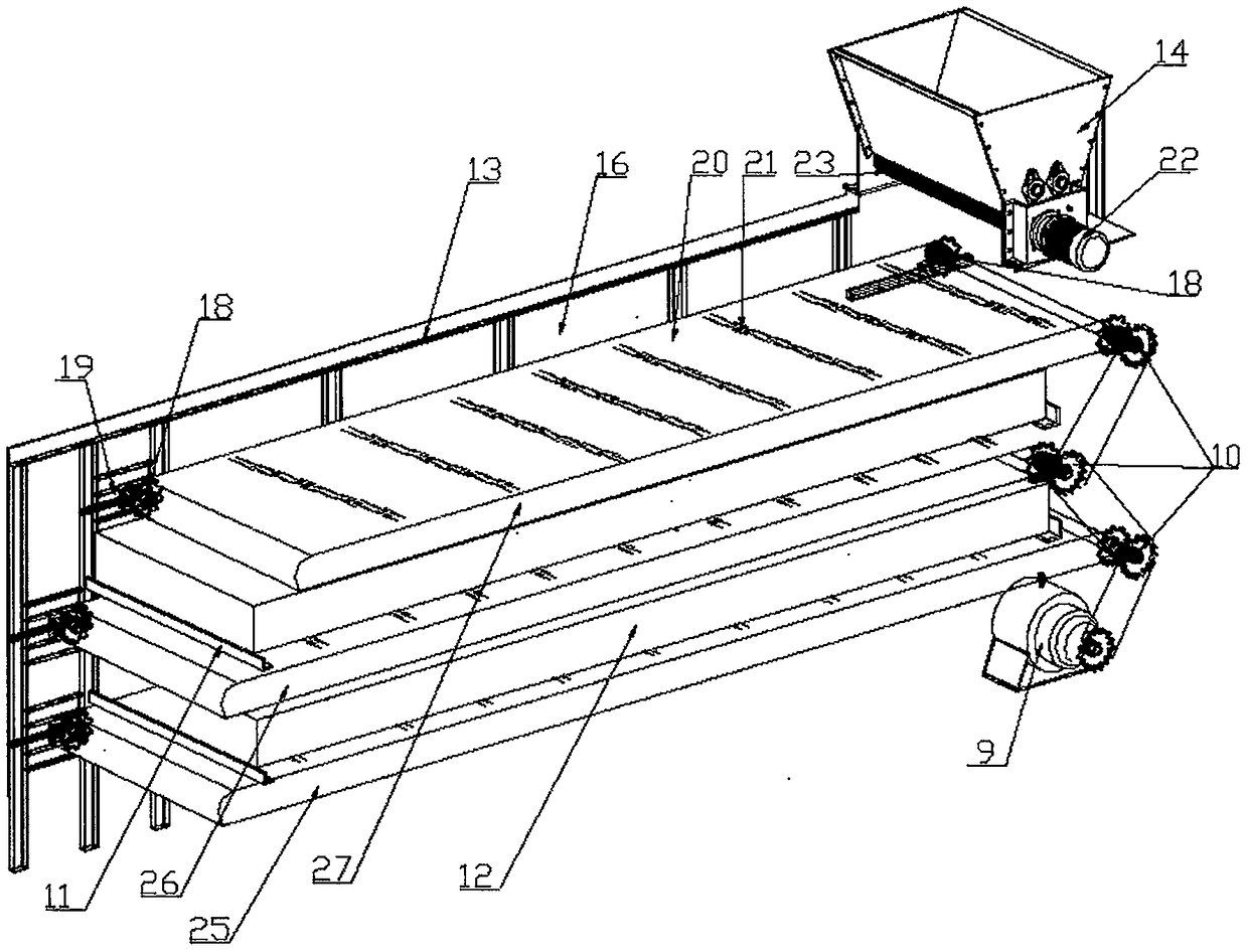
[0020] As shown in the figure, an oily sludge treatment machine includes a fixed frame 1, and the top of the fixed frame 1 is a sludge silo 2, and the inside of the sludge silo 2 is connected by an auger and an agitator 5. The described On the left side of the sludge silo 2 and on the front and rear sides of the mixer 5 are respectively provided an additive hopper 2, and the two additive hoppers 2 are respectively connected by the conveying auger 4 and the mixer 5, and the left bottom of the mixer 5 is It is connected with the conveyor belt hoist 6, and the conveyor belt hoist 6 is connected with the feed port of the sludge molding machine 14, and the sludge molding machine 14 pier is placed on the right end top of the sludge drying machine 13, and the sludge The top of the sludge dryer 13 is provided with at least two water vapor outlet pipes 7 to connect with the external waste gas treatment equipment 8 , and the bottom of the left end of the sludge dryer 13 is provided with ...


PUM


Abstract

The invention discloses an oily sludge treatment machine for an oil field. The machine comprises a fixed frame, wherein a sludge bin is arranged at the top of the fixed frame and connected with a stirrer, additive feeding hoppers are connected with front and rear sides of the stirrer respectively, the left side of the stirrer is connected with a conveying belt lifter, the conveying belt lifter isconnected with a feeding inlet of a sludge forming machine, the sludge forming machine is arranged on the top of the right end of a sludge drying machine, the sludge drying machine is connected with external waste gas treatment equipment by at least two steam outlet pipes arranged on the top of the sludge drying machine, and a discharging inclined plate is arranged at the bottom of the left end ofthe sludge drying machine. By means of the arrangement, forming and step-by-step drying operation of oily sludge are achieved, the oily sludge can be effectively treated and finally dried, and the waste gas generated in the drying process is directly discharged by the external waste gas treatment equipment. The oily sludge treatment machine is ideal.

Description

technical field [0001] The invention belongs to the technical field of sludge treatment equipment, and in particular relates to an oily sludge treatment machine used in oil fields. Background technique [0002] As we all know, in oil fields, oily sludge exists as a kind of petroleum appendages. This kind of oily sludge has various types and complex properties, and is listed as hazardous solid waste. Its treatment technology has increasingly attracted people's attention and attention. [0003] Due to the high viscosity of oily sludge, it is difficult to dry it using traditional drying methods and equipment such as drum dryers and paddle dryers. For this type of sludge, the commonly used drying technologies can be roughly divided into the following categories: Several: [0004] 1. Incineration method: This process causes serious secondary pollution, and the crude oil with high economic value in the sludge has not been recycled; 2. Pyrolysis method: This method has a fast proc...

Claims


Application Information

Patent Timeline
IPC IPC(8): C02F11/14
CPCC02F11/14
Inventor 陈桂兰
Owner 山东九择环保设备有限公司
Why Eureka
Try Eureka