Rapid CVD compacting method of carbon/carbon heat field structure product for single crystal furnace

A technology of carbon thermal field and single crystal furnace

Inactive Publication Date: 2018-06-29
AEROSPACE RUITIAN CARBON MATERIALS CO LTD
View PDF5 Cites 2 Cited by
  • Summary
  • Abstract
  • Description
  • Claims
  • Application Information

AI Technical Summary

Problems solved by technology

[0005] The method of the present invention proposes a combined furnace method for products with a single crystal thermal field structure, and adds an air field and temperature field design to solve the problem of low independent production of a single product while maintaining high deposition efficiency and realizing high single crystal thermal field products. Efficient output, greatly reducing production costs

Method used


Image

  • Rapid CVD compacting method of carbon/carbon heat field structure product for single crystal furnace
  • Rapid CVD compacting method of carbon/carbon heat field structure product for single crystal furnace
  • Rapid CVD compacting method of carbon/carbon heat field structure product for single crystal furnace

Examples


Embodiment 1

[0030] Embodiment 1 A method for rapid CVD densification of carbon / carbon thermal field structure products for single crystal furnaces, comprising the following steps:

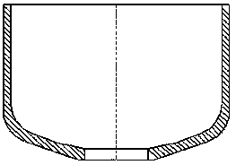
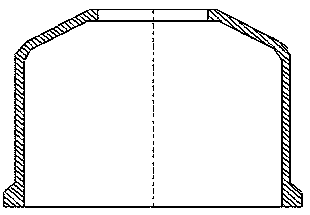
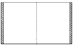
[0031] (1) Assembling the thermal field of the single crystal furnace: the thermal field of the single crystal furnace includes graphite tray 8, gas distribution tool 7, heat preservation cylinder 2, flow guide tube 4, crucible 3, gas guide cylinder 5, and gas limiting tool 1; The graphite material tray 8 and the gas distribution tool 7 are located at the bottom of the thermal field of the single crystal furnace, and an insulation tube 2 is arranged on it. The inside of the insulation tube 2 is provided with a guide tube 4 and a crucible 3, and the guide tube 4 is located in the crucible. 3, the air-guiding tube 5 passes through the hole at the bottom of the center of the crucible 3 and the air-guiding tube 4, and the gas-limiting tool 1 is arranged above the insulating tube 3. During design, the thickness of ...

Embodiment 2

[0035] (1) Assembling the thermal field of the single crystal furnace: the thermal field of the single crystal furnace includes graphite tray 8, gas distribution tool 7, heat preservation cylinder 2, flow guide tube 4, crucible 3, gas guide cylinder 5, and gas limiting tool 1; The graphite material tray 8 and the gas distribution tool 7 are located at the bottom of the thermal field of the single crystal furnace, and an insulation tube 2 is arranged on it. The inside of the insulation tube 2 is provided with a guide tube 4 and a crucible 3, and the guide tube 4 is located in the crucible. 3, the air-guiding tube 5 passes through the hole at the bottom of the center of the crucible 3 and the air-guiding tube 4, and the gas-limiting tool 1 is arranged above the insulating tube 3. During design, the thickness of the graphite material tray 7 is not less than 50 mm, and the thickness of the gas distribution tool 6 is not less than 40 mm, both of which are made of graphite; There is...


PUM

PropertyMeasurementUnit
thicknessaaaaaaaaaa
thicknessaaaaaaaaaa

Abstract

The invention discloses a rapid CVD compacting method of a carbon/carbon heat field structure product for a single crystal furnace. The rapid CVD compacting method comprises the following steps: (1) assembling a single crystal furnace heat field, wherein the single crystal furnace field comprises a graphite charging tray, an air manifold tool, a insulated barrel, a guiding barrel, a crucible, an air guiding barrel, and an air limiting tool; (2) CVD compacting; (3) repeating the step (2), and repeatedly compacting for multiple times until the density is not less than 1.35g/cm<3>. The rapid CVDcompacting method has the following beneficial effects: 1, by innovatively adding an airflow control element and integrating the advantages of the small-distance (slit flow and narrow flow) depositionand air guiding deposition, the method has the characteristic of high deposition efficiency, the cost is decreased, and the production period is shortened; 2, the furnace is innovatively assembled according to the appearance characteristics of the product, so that the product loading capacity can be greatly increased, and the yield is increased; and 3, the method has the characteristics of high practicability and easy in mass production and popularization and is easy to accept by single crystal heat field manufacturers.

Description

technical field [0001] The invention belongs to the field of chemical vapor deposition, and in particular relates to a rapid CVD densification method for a carbon / carbon thermal field structure product used in a single crystal furnace. Background technique [0002] Among the existing densification methods, the C / C composite material is prepared by CVD process, which has outstanding advantages such as high temperature resistance, excellent mechanical properties, stable chemical properties, and no pollution to high-purity semiconductor materials. The chemical vapor deposition (CVD) process is the earliest C / C composite technology. The carbon fiber fabric prefabricated body is placed in a special CVD furnace, heated to the required temperature, and hydrocarbon gas is introduced. These gases are decomposed and deposited on the Carbon is deposited around and in the voids of the carbon fiber fabric. [0003] Carbon / carbon heat field structure products for single crystal furnaces ...

Claims


Application Information

Patent Timeline
Patent Type & Authority Applications(China)
IPC IPC(8): C04B35/84C04B35/83
CPCC04B35/83C04B2235/77
Inventor 姜召阳曹磊罗昆鹏陈小飞张贵歧高晓佳王春梅崔树永
Owner AEROSPACE RUITIAN CARBON MATERIALS CO LTD
Why Eureka
Try Eureka