
Textile Dyeing Unit

A dyeing device and textile technology, applied in the direction of textiles and papermaking, equipment configuration for processing textile materials, processing of textile materials, etc., can solve the problems of textile wear, affecting the quality of textiles, poor dyeing effect, etc., achieve uniform dyeing, and promote absorption , Improve the effect of dyeing efficiency

Active Publication Date: 2020-04-21
NINGBO WENZE TEXTILE CO LTD
View PDF5 Cites 4 Cited by
  • Summary
  • Abstract
  • Description
  • Claims
  • Application Information

AI Technical Summary

Problems solved by technology

[0004] Although the above-mentioned patented solution solves the deficiencies in the traditional dyeing method, there are still some points to be improved: 1. During the dyeing process, the textile simply moves with the turntable in the dye box, and then leaves the dye vat, This kind of self-dyeing in a short time leads to poor dyeing effect; 2. Scraping off excess dye on the textile through the extrusion device is easy to cause wear and tear on the textile and affect the quality of the textile

Method used


Image

  • Textile Dyeing Unit
  • Textile Dyeing Unit
  • Textile Dyeing Unit

Examples


Embodiment Construction

[0023] The present invention will be described in further detail below by means of specific embodiments:

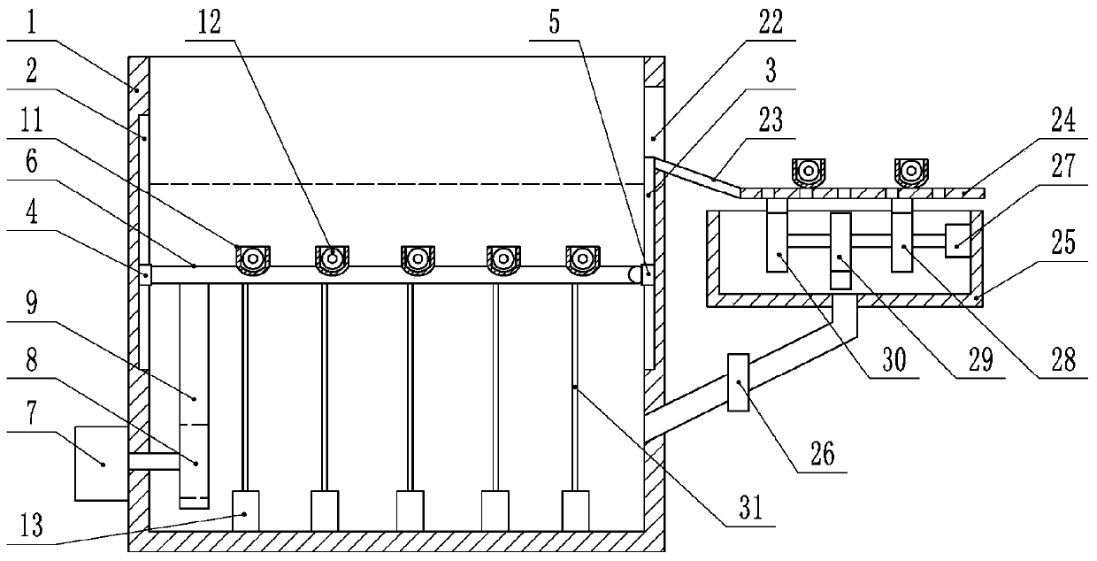
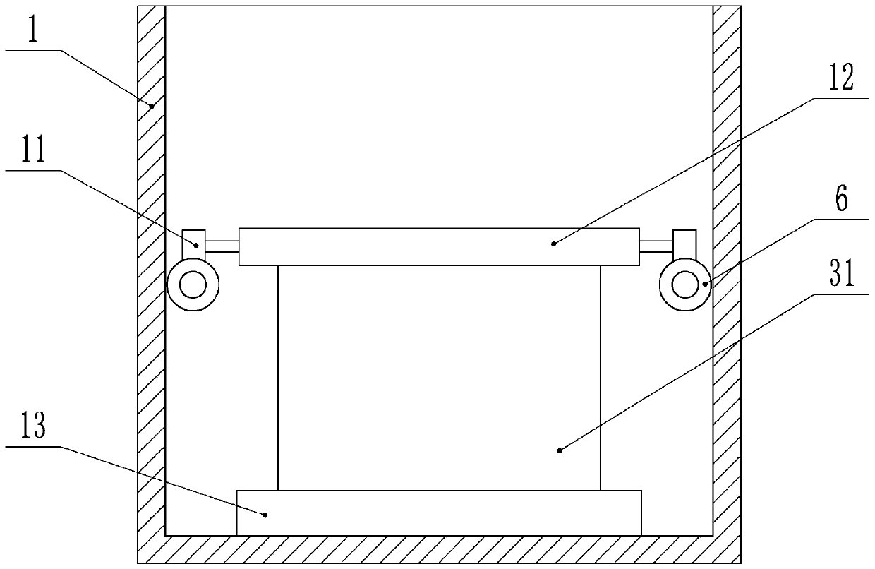
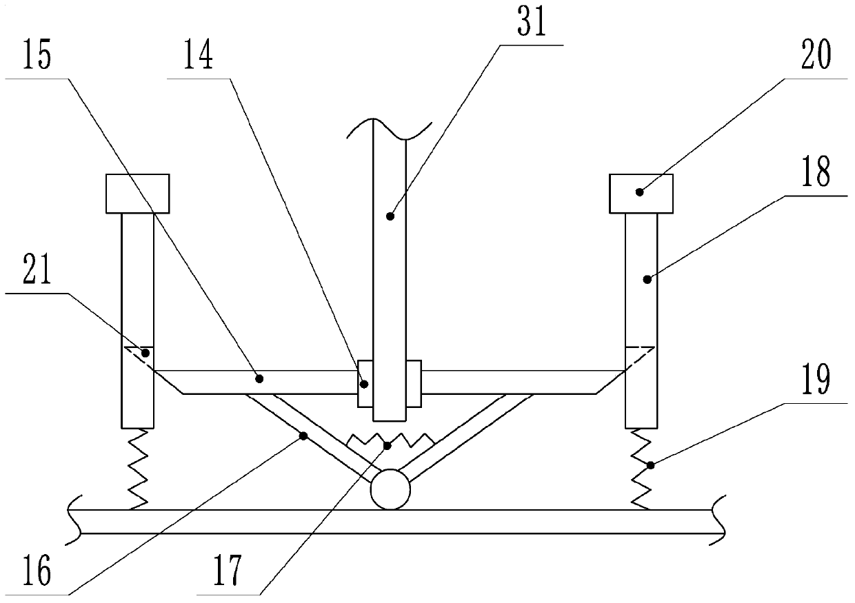
[0024] The reference signs in the drawings of the description include: dyeing box 1, first chute 2, second chute 3, first slider 4, second slider 5, guide roller 6, first motor 7, gear 8 , rack 9, limit groove 10, loading frame 11, coil roll 12, fixing mechanism 13, splint 14, wedge bar 15, connecting rod 16, first spring 17, slide bar 18, second spring 19, the first An electromagnet 20, wedge groove 21, discharge port 22, material guide plate 23, elastic filter screen 24, recovery tank 25, one-way valve 26, second motor 27, first cam 28, second cam 29, third Cam 30, textile 31.

[0025] This embodiment is basically as attached Figure 1 to Figure 4 Shown:

[0026] The textile dyeing device comprises a dyeing box 1, and a first chute 2 and a second chute 3 are provided on the inner wall of the dyeing box 1 (such as figure 1 shown), the top of the first chute 2 is high...


PUM


Abstract

The invention relates to the technical field of textile processing and discloses a textile dyeing device. The textile dyeing device comprises a dyeing box, wherein a first sliding chute and a second sliding chute are formed in the dyeing box, the first sliding chute is slidably connected with a first sliding block, the second sliding chute is slidably connected with a second sliding block, two material guiding rollers are slidably connected in the dyeing box, a limit slot is formed in each material guiding roller, an object carrying frame is arranged in each limit slot, a material rolling roller is rotatably connected in each object carrying frame, a fixing mechanism is arranged in the dyeing box, the fixing mechanism comprises two clamping plates, each clamping plate is fixedly connectedwith a wedge rod, each wedge rod is fixedly connected with a connecting rod, two connecting rods are hinged on the inner wall of the dyeing box, two sliding rods are slidably connected in the dyeing box, a first electromagnet is arranged on each sliding rod, and a second electromagnet is arranged on the inner wall of the dyeing box; a discharging hole is formed in the dyeing box, a touch switch isarranged at the discharging hole, the discharging hole is connected with a material guiding plate, the material guiding plate is connected with a hollow elastic filter screen, and a recycling tank isconnected below the elastic filter screen. The textile dyeing device disclosed by the invention can rapidly and uniformly carry out dyeing.

Description

technical field [0001] The invention relates to the technical field of textile processing, in particular to a textile dyeing device. Background technique [0002] Textiles need to be dyed in the production process for aesthetics. The quality of dyeing directly affects the value of textiles, and the dyeing process is very important. The traditional dyeing method is to put the textile into the dyeing equipment and let it permeate and dye by itself. The efficiency is relatively low. After the dyeing is finished, there will be a large amount of dye on the textile, which not only prolongs the drying time of the dyed cloth, but also causes the dye to waste. [0003] In order to solve the above problems, Chinese patent (CN107401012A) discloses a dyeing device for textile processing, which includes a box body, a dye box is fixedly connected to one side of the inner wall of the box, and a first motor is fixedly connected to the bottom of the inner wall of the box. The output shaft ...

Claims


Application Information

Patent Timeline
Patent Type & Authority Patents(China)
IPC IPC(8): D06B3/10D06B15/00D06B23/04D06B23/20
CPCD06B3/10D06B15/00D06B23/04D06B23/20
Inventor 许根海
Owner NINGBO WENZE TEXTILE CO LTD
Learn More