Supercharge Your Innovation With Domain-Expert AI Agents!

Multi-pipe efficient easy-installing exhaust pipe structure

An exhaust pipe, easy-to-install technology, used in exhaust devices, mufflers, engine components, etc., can solve the problems of heat accumulation in the exhaust pipe, affecting the life of the exhaust pipe, environmental pollution, etc., to prolong the service life, prevent Heat build-up, the effect of improving durability

Inactive Publication Date: 2018-06-29
张振飞
View PDF0 Cites 0 Cited by
  • Summary
  • Abstract
  • Description
  • Claims
  • Application Information

AI Technical Summary

Problems solved by technology

The existing exhaust pipe is usually a pipe, because the diameter of the exhaust pipe cannot be enlarged at will. Therefore, for an engine with a large displacement, when the engine is running at a high speed, the gas discharge will not be timely. It is easy to cause heat accumulation in the exhaust pipe, which affects the life of the exhaust pipe. When the engine is running at low speed, the incompletely burned fuel is directly discharged, resulting in energy loss and easy to cause environmental pollution.

Method used


Image

  • Multi-pipe efficient easy-installing exhaust pipe structure
  • Multi-pipe efficient easy-installing exhaust pipe structure
  • Multi-pipe efficient easy-installing exhaust pipe structure

Examples


Embodiment 1

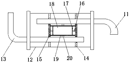
[0025] In Embodiment 1, when the device is in use, when the engine is running at a low speed, the temperature of the exhaust gas is relatively low, the volume change of the airbag 18 is small, and the gap between the first partition 14 and the second partition 15 is small. The back pressure will prevent the exhaust gas from rushing out, and the exhaust gas will return to the inside of the engine, so that the mixture can be completely burned, saving fuel, and reducing the burden on the exhaust gas purification device. When the engine is running at high speed, the temperature of the exhaust gas is relatively high. The volume of the airbag 18 changes greatly, and the first partition 14 is separated from the second partition 15. At this time, the waste gas can be smoothly discharged from the device, preventing heat accumulation inside the device and prolonging the service life of the device.

Embodiment 2

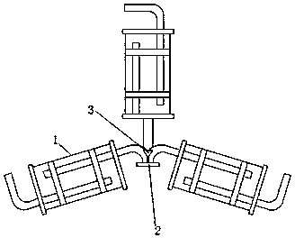
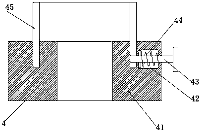
[0026] In Embodiment 2, when the device is installed, it is connected to the engine through the anti-loosening nut 4 on the triangular flange 2, and then connected to the bracket through the hanging piece 20. The installation is convenient and simple, and the anti-loosening nut 4 can prevent it from being connected to the device. The screw falls off, which avoids the frequent vibration of the device and causes the screw to fall off, and improves the durability of the device. The reinforcement plate 3 can strengthen the strength of the device itself. When the screw is connected to the anti-loosening nut 4, pull the adjustment lever first The handle on the 43 takes out the baffle plate 45, and after the screw is screwed, install the baffle plate 45, and the adjusting rod fixes the baffle plate 45 under the action of the second spring 44, and the baffle plate 45 limits the rotation of the screw to prevent the screw fall off.


PUM


Abstract

The invention discloses a multi-pipe efficient easy-installing exhaust pipe structure comprising short barrel type exhaust pipes. A triangular flange is welded between the short barrel type exhaust pipes, reinforcing plates are welded to the two sides of the joint of the short barrel type exhaust pipes and the triangular flange, and the triangular flange is provided with an anti-off nut. When themulti-pipe efficient easy-installing exhaust pipe structure is used and an engine runs at a low speed, the temperature of tail gas is low, the size of a gasbag changes little, the gap between a firstseparation plate and a second separation plate is small, at the moment, return pressure in the pipes prevent waste gas from rushing out, mixed gas reaches complete combustion, fuel is saved, and the burden of a tail gas purification device is reduced. When the engine runs at a high speed, the temperature of tail gas is high, size change of the gasbag is large, the first separation plate and the second separation plate are separated, at the moment, waste gas can be discharged from the device, heat accumulation in the device is prevented, and service life of the device is prolonged.

Description

technical field [0001] The invention relates to the technical field of exhaust pipes, in particular to a multi-pipe exhaust pipe structure with high efficiency and easy installation. Background technique [0002] The exhaust pipe is installed between the engine exhaust manifold and the muffler, so that the entire exhaust system is flexibly connected, thereby reducing vibration and noise, facilitating installation and prolonging the life of the exhaust muffler system. The existing exhaust pipe is usually a pipe, because the diameter of the exhaust pipe cannot be enlarged at will. Therefore, for an engine with a large displacement, when the engine is running at a high speed, the gas discharge will not be timely. It is easy to cause heat accumulation in the exhaust pipe and affect the life of the exhaust pipe. When the engine is running at a low speed, the incompletely burned fuel is directly discharged, resulting in energy loss and easy to cause environmental pollution. Cont...

Claims


Application Information

Patent Timeline
Patent Type & Authority Applications(China)
IPC IPC(8): F01N13/08F01N13/18
CPCF01N13/08F01N13/1805F01N13/1855
Inventor 张振飞
Owner 张振飞
Features
  • R&D
  • Intellectual Property
  • Life Sciences
  • Materials
  • Tech Scout
  • Unparalleled Data Quality
  • Higher Quality Content
  • 60% Fewer Hallucinations
Learn More