
Depth-controllable rock sample drilling device and utilization method

A technology for rock test pieces and drilling devices, which is applied in the direction of working accessories, stone processing tools, stone processing equipment, etc., can solve problems such as drill sticking, surface damage of holes and test pieces, and deviations in test results, so as to improve work efficiency. Efficiency, reliable measurement, and the effect of overcoming stuck pipe

Inactive Publication Date: 2018-07-06
SHANDONG UNIV OF SCI & TECH
View PDF6 Cites 6 Cited by
  • Summary
  • Abstract
  • Description
  • Claims
  • Application Information

AI Technical Summary

Problems solved by technology

[0003] Existing treatment methods for test piece holes: one is to reserve holes in advance, that is, during the test piece production process, insert a smooth plastic or iron rod into the test piece mold, and pull it out after the material is solidified. The method requires that the rod must be kept in a vertical state until the material is solidified. During this process, the placed rod needs to be rotated continuously to prevent the rod and material from being difficult to pull out after solidification, which increases the difficulty of making the test piece. Time-consuming and labor-intensive; Another method is to use ordinary drilling equipment to drill the sampled or prepared specimens. This method is difficult to keep the drill pipe and the hole in a straight line during the drilling process, resulting in The diameter of the hole is different, and the depth of the drilling is difficult to accurately determine, and there are obvious limitations.
Ordinary drilling equipment cannot effectively control the speed and propulsion force of the drill pipe, and it is prone to drill sticking. Improper handling will destroy the integrity of the test piece in advance, resulting in deviations from the actual test results.
In addition, affected by the size of the test piece during the drilling process of the test piece, it is easy to cause damage to the hole and the surface of the test piece during the process of drilling through holes, and there is also the problem that the large amount of drilling dust affects the working environment

Method used


Image

  • Depth-controllable rock sample drilling device and utilization method
  • Depth-controllable rock sample drilling device and utilization method
  • Depth-controllable rock sample drilling device and utilization method

Examples


Embodiment 1

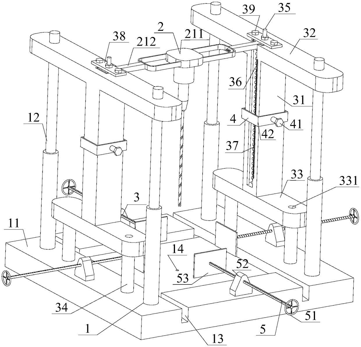
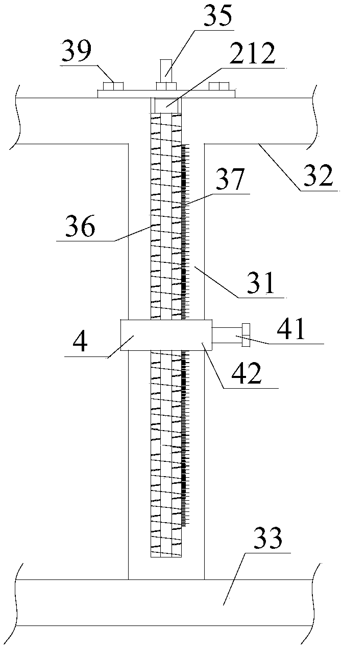
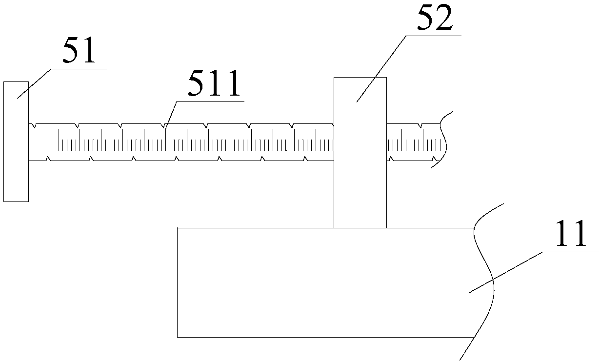
[0028] Such as Figure 1 to Figure 5 As shown, this embodiment is a specific description of the structure of the depth-controllable rock specimen drilling device.

[0029] A depth-controllable drilling device for a rock test piece specifically includes a vertical frame 1 , a drilling mechanism 2 , an I-shaped slideway mechanism 3 , a caliper mechanism 4 and a displacement mechanism 5 . Wherein the I-shaped slideway mechanism 3 is fixed on both sides of the vertical frame 1, the drilling mechanism 2 moves up and down along the slideway 31 of the I-shaped slideway mechanism through the connecting handle 212, and the displacement mechanism 5 is fixed on the bottom of the vertical frame 1 , the caliper mechanism 4 moves along the slideway outside the slideway 31.

[0030] Wherein, the drilling mechanism 2 specifically includes a drilling machine driving unit 21, a drilling machine 211 and a connecting handle 212, and the drilling mechanism is connected with the I-shaped slideway ...

Embodiment 2

[0036] Such as Figure 6 and Figure 7 As shown, this embodiment is a specific description of the method of using the depth-controllable rock specimen drilling device in embodiment 1.

[0037] The drilling method using a depth-controllable rock test piece drilling device, the specific steps include:

[0038] The first step is to fix the specimen, and select a plane splint or an arc splint according to the shape of the specimen 6: if it is a square specimen, fix the plane splint on the push rod; It is fixed on the push rod 51; after the splint 53 is fixed, the test piece is fixed by the push rod 51 and the splint 53; the square and cylindrical test pieces can be fixed by using the plane splint or the curved splint, which improves the drilling of different test pieces. work efficiency.

[0039] The second step is precise positioning. According to the needs of drilling corresponding positions on the test piece, the drilling depth h is determined, and the push rod 51 on the fro...


PUM


Abstract

The invention discloses a depth-controllable rock sample drilling device and a utilization method. The problem about accurately drilling rock samples of different shapes is solved. The drilling devicecomprises a vertical rack, a drilling mechanism, an I-shaped slide mechanism, a caliper mechanism and a displacement mechanism, wherein pushing rods are arranged on a base of the vertical rack; the samples are fixed through the pushing rods; the pushing rods are provided with scales, so that the samples are accurately moved; clamping plates are arranged in front of the pushing rods; the clampingplates are changed to adapt to the samples of different shapes; and a through hole is formed in the center of the base of the vertical rack. According to the depth-controllable rock sample drilling device, holes of the processed samples are protected; stress springs are arranged in the slide mechanism, drilling force is controlled, and the drill sticking problem is avoided; and the outer surfacesof slides and the caliper mechanism are provided with scales, so that the drilling position and drilling depth are accurately controlled. The invention further discloses an operation method for drilling the rock samples of different shapes at different depths.

Description

technical field [0001] The invention relates to a rock test piece drilling device and a use method, in particular to a rock test piece drilling device with controllable depth and different shapes and a use method. Background technique [0002] A relatively large number of mines in my country have been mined below 1,000 meters, so dynamic disasters such as rock bursts have increased significantly, seriously restricting the safe and efficient mining of deep coal resources. Practice has shown that drilling pressure relief is an efficient measure for rock burst relief. The indoor research on the mechanism of drilling pressure relief provides a basis for better performance of drilling pressure relief on site; the circular roadway is a coal mine A commonly used roadway form, the indoor research on the internal deformation law of circular roadway and the mechanical characteristics of surrounding rock has important guiding significance for the selection of reasonable support paramet...

Claims


Application Information

Patent Timeline
Patent Type & Authority Applications(China)
IPC IPC(8): B28D1/14B28D7/04B28D7/00B28D7/02G01N1/28
Inventor 徐强顾清恒谭云亮宁建国马庆王军邱鹏奇姜宁
Owner SHANDONG UNIV OF SCI & TECH
Learn More