
Fine metal mask plate, preparation method thereof and mask integrated framework

A fine metal mask and mask plate technology, which is applied in metal material coating process, printed circuit manufacturing, photoplate making process of pattern surface, etc., can solve the problem of pattern edge deviation and other problems

Active Publication Date: 2018-07-06
BOE TECH GRP CO LTD
View PDF3 Cites 11 Cited by
  • Summary
  • Abstract
  • Description
  • Claims
  • Application Information

AI Technical Summary

Problems solved by technology

[0005] Embodiments of the present invention provide a fine metal mask, a preparation method thereof, and a mask integration frame, which can solve the problems of forming a film layer due to wrinkles generated on the mask in the mask evaporation process of the existing mask. The problem that the edge of the pattern is deviated

Method used


Image

  • Fine metal mask plate, preparation method thereof and mask integrated framework
  • Fine metal mask plate, preparation method thereof and mask integrated framework
  • Fine metal mask plate, preparation method thereof and mask integrated framework

Examples


preparation example Construction

[0064] Another aspect of the embodiments of the present invention provides a method for preparing a fine metal mask, such as Figure 7 shown, including:

[0065] S101 , making a mask pattern on the metal sheet to form a mask pattern region 11 .

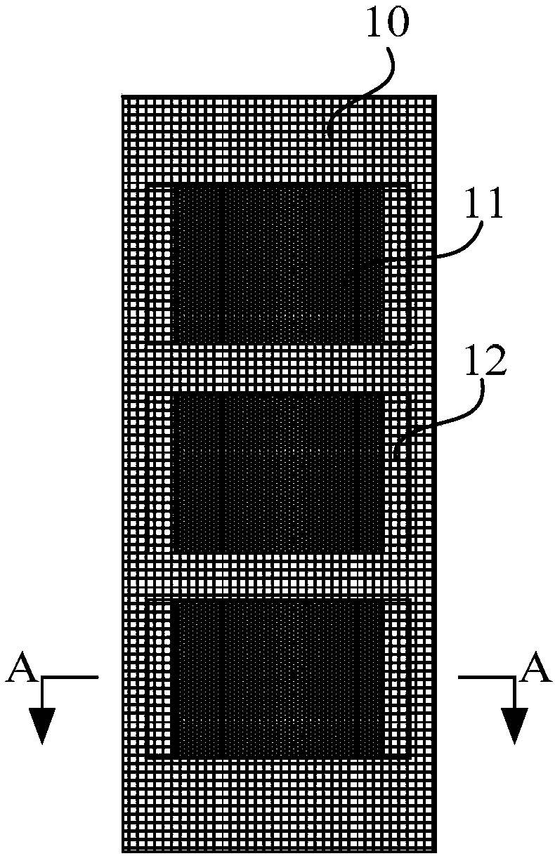
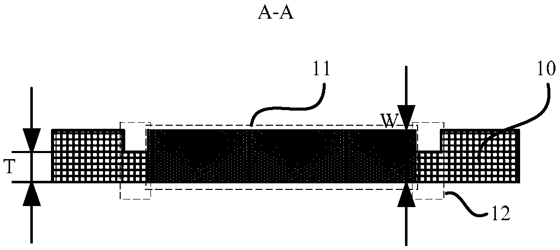
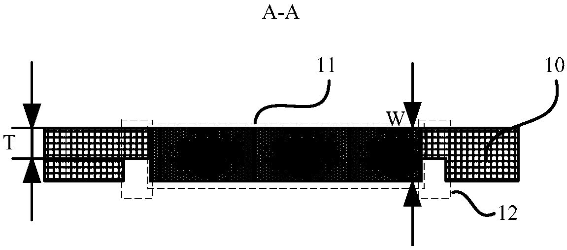
[0066] S102 , thinning at least one side surface of the metal sheet along at least one side edge of the mask pattern area 11 and in contact with the edge is located on at least one side surface of the fine metal mask 10 to form a protection area 12 .

[0067] Making the fine metal mask 10 of the embodiment of the present invention includes making two parts of the mask pattern region 11 and the protection region 12 on the metal sheet. It should be noted that, in the embodiment of the present invention, for making the mask pattern region 11 ( The order of step S101) and making the protected area 12 (step S102) is not specifically limited, and the mask pattern area 11 can be made on the metal sheet first, that is, step S101 is performed...


PUM


Abstract

The embodiment of the invention provides a fine metal mask plate, a preparation method thereof and a mask integrated framework and relates to the technical field of mask evaporating. The problem thatin the mask evaporating process of an existing mask plate, wrinkles generated on the mask plate make deviation occur on the edge of a pattern forming a film layer can be solved. A mask pattern area isarranged on the fine metal mask plate, the fine metal mask plate further comprises a protecting area along at least one side edge of the mask pattern area and connected with the edge, and the thickness of the protecting area is smaller than that of the mask pattern area.

Description

technical field [0001] The invention relates to the technical field of mask evaporation, in particular to a fine metal mask plate, a preparation method thereof, and a mask integration frame. Background technique [0002] The display device includes a plurality of pixel units arranged in an array, and each pixel unit includes sub-pixel units of three colors of red, green and blue (referred to as R / G / B sub-pixel units for short). Wherein, taking an OLED display device as an example, any sub-pixel unit specifically includes an anode layer, a hole transport layer, a light emitting layer capable of emitting red / green / blue light, an electron transport layer and a cathode layer. At present, the R / G / B sub-pixel units in OLED display devices are usually arranged in the side by side method. When preparing each sub-pixel unit, the mask technology is used. The shading effect of the area blocks the sub-pixel units of two colors in the R / G / B sub-pixel unit, and then deposits the film-for...

Claims


Application Information

Patent Timeline
IPC IPC(8): C23C14/04C23C14/24
CPCC23C14/042C23C14/24H10K71/166B05D1/32B05C21/005B05C17/06H01L21/308G03F1/64H05K3/1225C23C16/042H10K71/00H10K59/35
Inventor 张斌王新星周婷婷孙雪菲王伟杰朱海彬
Owner BOE TECH GRP CO LTD
Learn More